Following a post in the Eng-Tips Forum about finding the buckling load of a stepped strut I have modified the Frame4 spreadsheet to carry out a buckling analysis of any straight member subject to axial load, including stepped or tapered cross sections. The spreadsheet, including full open source code, may be downloaded from: Frame4Buckle.zip
The buckling load is found using the method of Vianello, described in a paper from the University of Ljubljana (Note 20 Nov 14: The link to the University no longer works, but the iterative procedure used is described in Theory of Elastic Stability by Timoshenko and Gere). This is an iterative method using successive approximations of the deflected shape:
- Assume an approximation of the deflected shape. In the spreadsheet a linear approximation is used from the fixed point(s) to the point of maximum deflection, which is assumed to be at the top of the column if the top is unrestrained in the X direction, or at mid height if the top is restrained.
- Find the bending moments due to a unit axial load applied at the top in a column with this shape .
- Find the deflections of a column subject to this bending moment distribution.
- Normalise the deflections based on the maximum absolute deflection.
- Update the column shape using the normalised deflections, and repeat the analysis.
- Repeat until the difference in maximum deflection between successive iterations is negligible.
- The buckling load is the inverse of the maximum deflection from the last iteration (before normalisation).
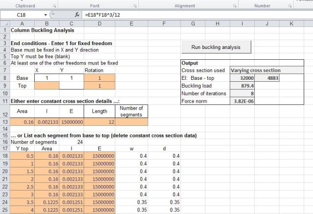
The Frame4 spreadsheet has been modified to generate the required input data and carry out the analysis simply and quickly for a straight member with axial load applied at one end. The input required is:
- End conditions: either 1 (fixed) or 0 (free) for base rotation, top X deflection and top rotation. X and Y deflection at the base must be fixed, and Y deflection at the top must be free.
- Cross section details: for a member of constant cross section specify the cross section area, second moment of area, and E (Young’s Modulus), and member length and number of sections in the analysis. For a varying cross section enter the section details for every cross section, with the height to the top of the section.
- If the number of sections is entered in the constant cross section data the constant cross section is used. If this cell is blank or zero the varying cross section data table is used.
Typical input and results are shown in the screen shot below:
The buckling shape may be plotted to a chosen scaled deflection:
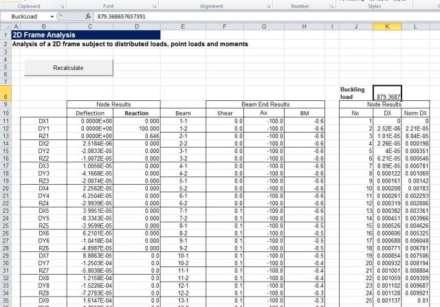
Calculated deflections and normalised deflections are listed on the “Output” sheet:


Dear Sir/Madam,
I have seen the buckling analysis spreadsheet and it is very useful resource. What is the reason for the end condition limitation? The spreadsheet is developed for end condition fixed or free can this be used for pinned conditions?
With Regards
EB
LikeLike
Sorry dougaj4
Could you share a version for Excel 2003?
LikeLike
I have added an xls file to the download zip file, but I haven’t tested it on Excel 2003. Please let me know if it works, or any problems.
LikeLike
I’ll do it soon.
Thanks a lot Doug
LikeLike
Sorry Douga
In sheet Buckle what are [w] and [d]?
And more: how many elements can i model’
Can I put, for example, 300 elements of 0.1 cm to model a tapered pole?
Thank you very much
LikeLike
(I wrong: 0.1 meter 😉 )
LikeLike
4step – The answers to most of your questions are in the blog post, but:
w and d are width and depth, used to calculate I (second moment of area). If you have a tapered section you need to enter the I value for each section in column C, but how you calculate it is up to you. The formula in the example is for a circular section, but you can change it to whatever you want, or calculate elsewhere and copy and paste.
Important:- if you want a tapered section you must delete the number of segments in cell E15.
For maximum number of sections, just see what works. For the Excel 2003 version it is quite a small number (about 50), but this is really all you need. There is no reason to have as many as 300 segments for this calculation.
LikeLike
Elizabeth – for stability the column must be fixed in the x and y directions at at least one end, and for buckling to occur it must be free in the y direction at one end (and fixed at the other). For simplicity I have fixed the base in the x and y directions and specified the top should be free in the y direction, but this doesn’t prevent pinned conditions. For pinned both ends enter a 1 under X top, and make sure that rotation top and bottom are blank. It should be possible to model any stable support conditions, although it may be necessary to invert the strut if it is tapered and the base is free in the x direction.
LikeLike
although it may be necessary to invert the strut if it is tapered and the base is free in the x direction.
Forget that bit!
Movement is relative, so a column restrained against horizontal movement at the base and free at the top will have the same buckling load as an identical column restrained horizontally at the top and free at the base.
Restraint against rotation must be applied at the correct end (for a tapered column) though.
LikeLike
Pingback: Buckling of rings and arches | Newton Excel Bach, not (just) an Excel Blog
what is the best cross section for a column?and why?
LikeLike
I think Dinah should be careful about getting other people to do her school homework.
LikeLike
Dinah – it depends on the loading and materials, amongst other things, but for a column with increasing vertical load from top to bottom, and hrizontal loads from any direction “tree shaped” is pretty good; i.e. a tapering circular section.
LikeLike
Pingback: Daily Download 1: Buckling of columns, rings and arches | Newton Excel Bach, not (just) an Excel Blog
Can someone please help me setup a buckling analysis with this…
Member is fixed/free axial loaded
7″L of 1.5″ diameter
Then quick taper down to
286″ L of .875″ diameter
The taper back up to:
7″L of 1.5″ diameter.
Steel. Very long and thin piece of steel rod (clearly)
LikeLike
Jon – I have set up the buckling analysis at:
http://interactiveds.com.au/software/Frame4buckle-Jon.xlsb
(I have converted units to metres and kNewtons, sorry)
Also I have set up both ends as fixed against rotation, but just delete any restraints you don’t want.
Note that the stiffer end segments only increases the calculated buckling load from 1.64 kN to 1.79 kN.
The Euler buckling load, using the thinner section over the complete length, is 1.63 kN.
LikeLike
did anybody already entered the real weight of the beams into the analisys?
LikeLike
Marco – this analysis assumes all the load is concentrated at the top, it would not be applicable to a situation where the column self-weight was significant.
It would be conservative to simply deduct the column weight from the buckling load, or for a more accurate estimate it would probably be simplest to do an incremental load analysis in a frame analysis program, including 2nd order effects.
LikeLike
Pingback: Using Frame4Buckle with the Alglib solver | Newton Excel Bach, not (just) an Excel Blog
I’ve tryed a test from an old book of Giovanni QUATTORDIO.

It seems good.
Could you take a look on my file, Dougaj4? https://app.box.com/s/x58axc6564ty50ll6xra
With Regards
LikeLike
Hi,
is it possible to get the calculation procedure?
Marco
LikeLike
Marco – The calculation procedure is given in the original post. Was there any particular aspect you wanted more information about?
LikeLike
Hi Doug,
I am looking for a formula for deflection of a hollow tapered pole with hexadecagon (16 sided) polygon. How can the spreadsheet be modified to do this calculation?
LikeLike
Using 24 (or more) stepped sections would give a pretty good approximation to a taper, so you just need to enter formulas in the Area and I (2nd Moment of Area) columns for a hexadecagon. You can enter the diameter and thickness in columns E and F. If you need a formula for I and A, my Section Properties spreadsheet has them for a Hollow regular n sided polygon, so just set n to 16.
Please ask if anything isn’t clear.
LikeLike
Thanks Doug.
Just a couple more questions:
– Where are the actual deflection distance values used to plot the figure in the ‘Plot’ worksheet? Is it Column L in the ‘Output’ worksheet?
– Is the buckling due to a vertical force on the column? I am actually working on deflection of a light pole due to lateral wind load. Does this spreadsheet apply to lateral wind load? How do you convert the wind speed data to the lateral load in Newtons?
– I also need to model the deflection of the light pole due to thermal radiation (i.e. the result of buckling due to temperature differential on the hot and cold side of the pole). Does this spreadsheet provide a close solution for this problem?
I would appreciate if you could point me in the direction to solve these problems.
Regards and thanks,
Manoj
LikeLike
The deflections for the plot are taken from Column C on the output sheet, multiplied by the scale factor on the Plot sheet.
Yes, the buckling is calculated for a point force at the top of the column. You can’t add in any other loads; it’s purely an Euler buckling calculation.
If you want to add in lateral loads, or even the self-weight of the pole, and you want to add in the effect of the deflections, you need to do a frame analysis. You could use the Frame4 spreadsheet (which the Frame4-buckle spreadsheet is based on):
To get the non-linear deformation effects you would need to set up an iterative process and regenerate the pole coordinates at each step. It is quite easy to set up manually, then you can automate with VBA if you want to.
For temperature related curvature you could calculate the deformed shape due to temperature strains and use that as the initial shape in your iterative analysis.
LikeLike
Pingback: Column buckling under multiple loads | Newton Excel Bach, not (just) an Excel Blog