
I have modified the ULS Design Functions spreadsheet, last presented here, to analyse sections subject to bi-axial bending, and non-symmetrical sections. The new version makes use of the routines for splitting any section defined by XY coordinates into trapezoidal layers, described here. The new version (ULS Design Functions-biax.xlsb) has been added to the zip file along with the previous version, and can be downloaded from ULS Design Functions.zip, including full open source code.
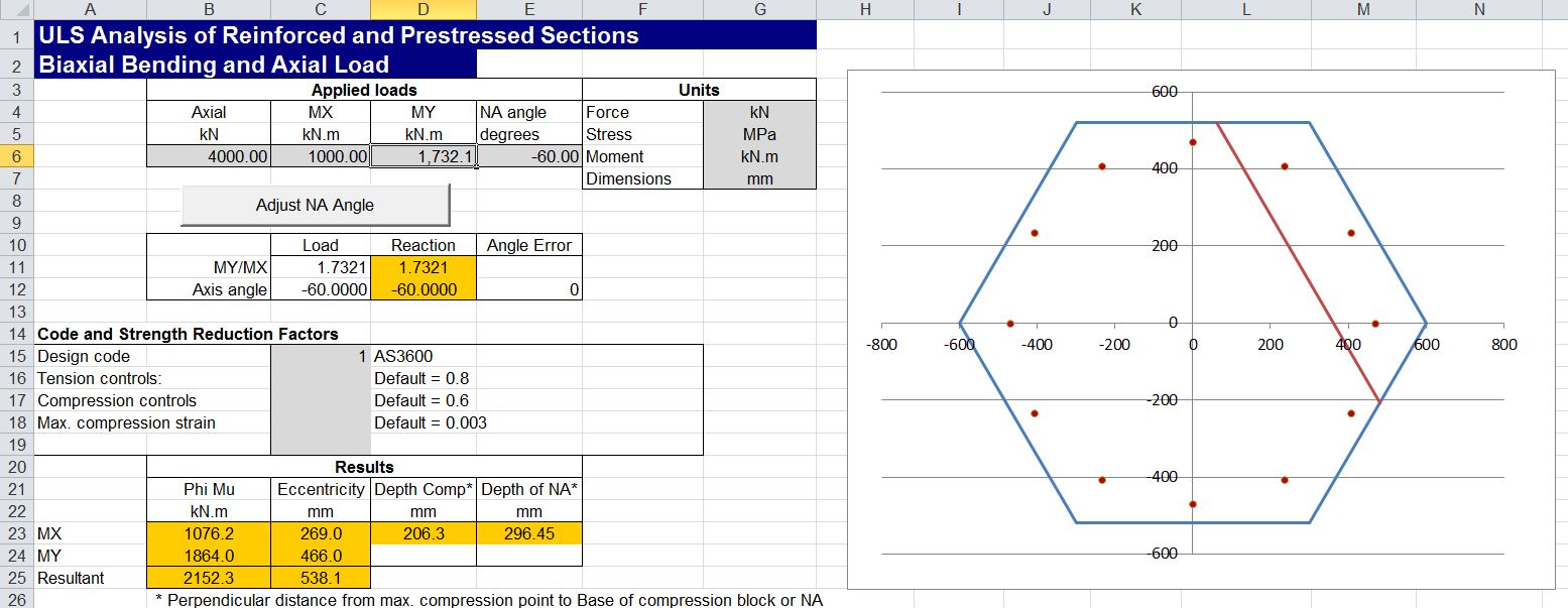
Input and results for a wide rectangular section, subject to bi-axial bending and axial load, are shown in the screenshot below:

The direction of the applied moment is defined by MX and MY, then the Neutral Axis angle is adjusted so that the reaction force and moments are in equilibrium with the applied loads, by clicking the “Adjust NA Angle” button.
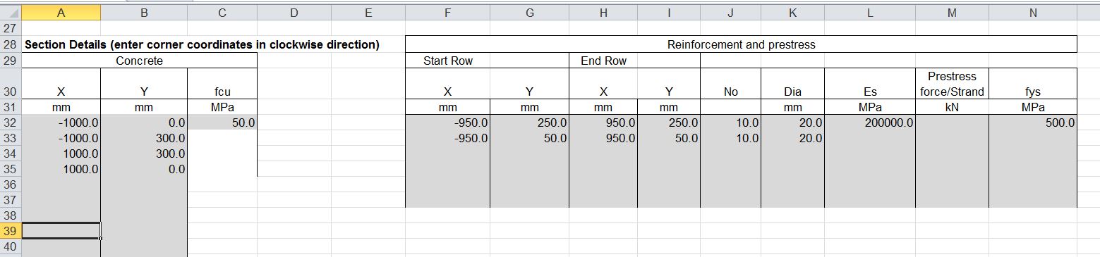
The concrete section is defined by XY coordinates of each corner, listed in a clockwise direction, and the reinforcement is defined in layers, by entering the coordinates of the start and end of each layer: For each layer the number of bars and bar diameter are defined, together with the steel properties for the first layer, and any subsequent layer with different properties. It is also possible to specify a prestress force for any layer.
The hexagonal section shown below demonstrates that for a symmetrical section the angle of the resultant moment axis is parallel to the Neutral Axis angle, as would be expected:
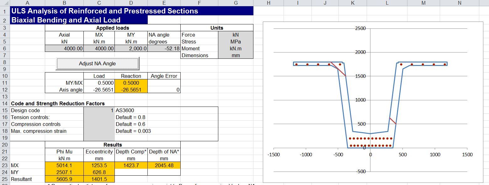
It is possible to define any complex shape, such as the precast Super-T bridge girder shown below:
It is also possible to define shapes with internal voids, as shown below, by listing the corners of the void in the anti-clockwise direction. In this case the line must be continuous from start to end, and the connection between the outer line and the void must be made with two separate lines, with a very small separation, so that separate lines do not overlap or cross at any point. See the example in the download file for more details.

More detailed output data is provided on the “UMom Out” sheet, in a similar format to the earlier version.
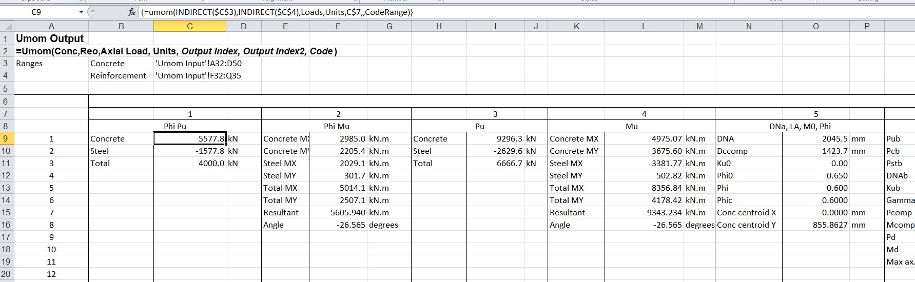
The analysis is carried out by two user defined functions (UDFs), UMom and UMomA. UMom provides the detailed output shown above for a single set of applied loads. UMomA returns any one of the available output values for a range of applied axial loads, and a single value or range of Neutral Axis directions. Both functions return an array of values, and must be entered as an array function, as described at Using Array Functions and UDFs.
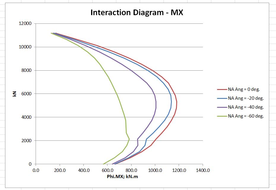
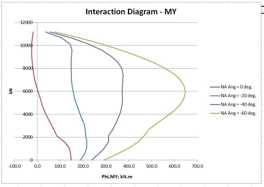
Use of the UMomA function allows the rapid generation of interaction diagrams, as shown in the screenshots below:

wow, great job
LikeLike
Hi,
Looks great. Thank you.
LikeLike
impressive! Immediately comes to mind to reuse procedure for finding NA in foundation pad also with corner uplift.
LikeLike
Pingback: Faster Biaxial Bending | Newton Excel Bach, not (just) an Excel Blog
When try to open biax spreadsheet got error in module mCoords Compile Error: Type mismatch.
(dPi As Double =)
LikeLike
This problem only in Excel 2016, in 2013 works OK.
LikeLike
Is your Excel 2016 64 bit? It works for me in 32 bit Excel 2016 (with 64 bit Windows).
It’s hard for me to fix 64 bit problems, because I don’t have it installed, but I have tried commenting out microtimer, which looks like it might be the source of the problem. You can download from:
http://interactiveds.com.au/software/ULS%20Design%20Functions-biax-no%20microtimer.xlsb
LikeLike
I use 32bit as well.
When open got same error, but I removed “” for dPi:
Const dPi As Double = 3.14159265358979 and now it is OK for me.
(For previous version when I removed “” Excel was closed totally with error)
LikeLike
That’s interesting. I’m not sure what’s going on there, but it looks like it might be time to review how I specify pi again.
LikeLike
Pingback: Year 10 Report | Newton Excel Bach, not (just) an Excel Blog
Hi there, can i use the same routine for unreinforced concrete sections and their evaluations. e.g. large unreinforced concrete earth retaining walls.
LikeLike
additionally …. do have background literature on calculation ….if that is possible as a student i would be really interested ….even background literature links would suffice
LikeLike
The routines are designed for reinforced sections. They might work for unreinforced, but I don’t guarantee it. If you try it, check that forces and moments are in equilibrium with the applied loads, and are consistent with the reported stresses.
For background information, try:
and the linked posts in that series.
Also try setting “category” to concrete near the top of the right margin.
LikeLike