
The reinforced concrete biaxial bending spreadsheet has now been updated:
- Stress block and capacity reduction factors updated for AS 3600-2018
- ACI factors for US customary units used when stress is entered in ksi or psi units
- Example data updated
The revised spreadsheet is included in the file:
ULS Design Functions.zip
I have checked the spreadsheet results against a paper published by Enercalc:
Reinforced Concrete Columns in Biaxial Bending
Enercalc results:
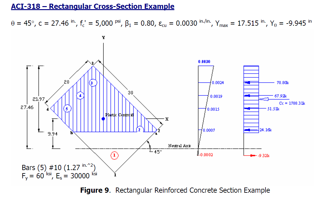
ULS Design Functions-biax results:
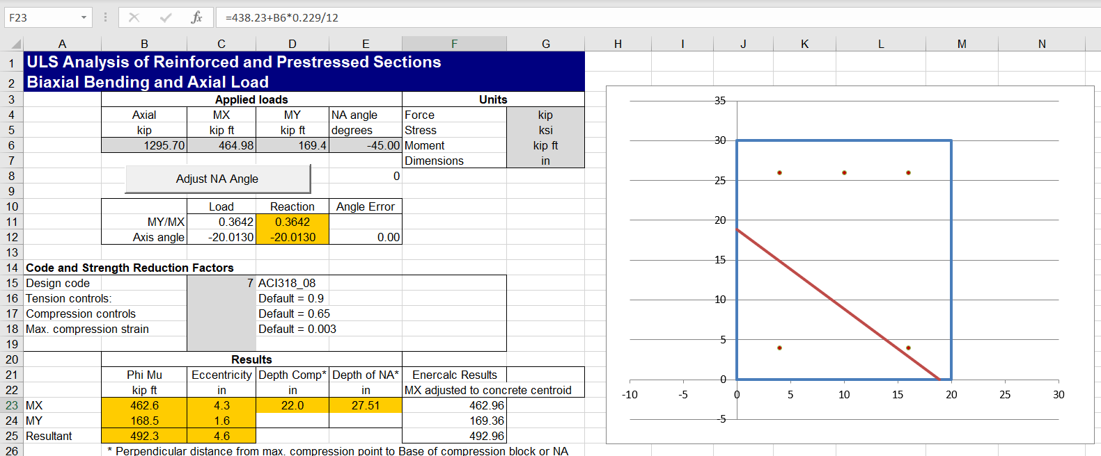
After adjusting the Enercalc moments to the centroid of the uncracked concrete section, the results are in near exact agreement.
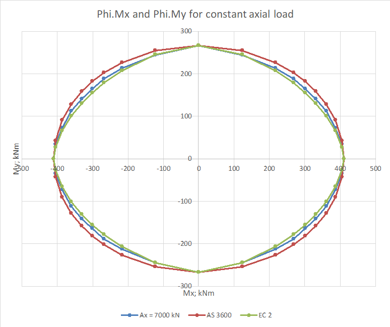
The results below compare the spreadsheet results with the simplified procedures given in AS 3600 and Eurocode 2, using a rectangular section and plotting moment capacity results under different axial loads:

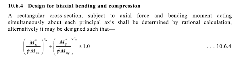
The AS 3600 and Eurocode provisions for biaxial bending take exactly the same form:
 The two codes give significantly different results however because:
- In AS 3600 the Phi factor is defined as 0.65 for all axial loads, whereas the Eurocode uses the design Mux and Muy values for the applied axial load.
- The definition of the exponent alpha is different, resulting in AS 3600 having a lower value for low axial loads, but a higher value for high axial loads.
For the purposes of comparison, the Eurocode Mx and My values used the design moment capacities under the applicable axial load to the AS 3600 rules.
For an axial load well below the balance load both codes have an alpha value of 1, resulting in conservative capacity values under biaxial loading. The AS 3600 requirement to use a Phi factor of 0.65 results in a further substantial conservatism:
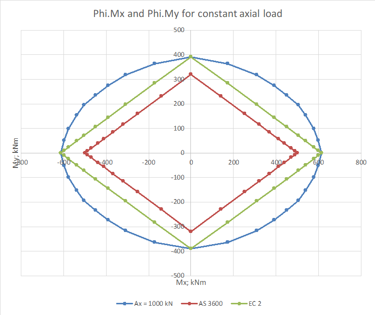
Increasing the axial load to close to the balance load increases the alpha values above 1, and brings the AS 3600 Phi factor down close to 0.65, reducing the conservatism of the simplified approach:

A further increase in the axial load increases the alpha value for AS 3600 to close to 2, so that the AS 3600 results are no longer conservative. The Eurocode alpha value is lower, and it is still conservative:

A further increase in the axial load shows the same trend, with the AS 3600 results increasingly unconservative, and the Eurocode results closer to the detailed calculation, but still conservative:
For very high axial loads, where the base of the rectangular stress block is outside the concrete section, there is a large reduction in the moment capacity from the detailed calculation. This is not reflected in the simplified method from either code, which both have an alpha value of 2 at these loads:

Further complications arise with non-rectangular sections:
In this case the simplified method from both codes gives results that are highly unconservative for some moment combinations, even for axial loads well below the design limit: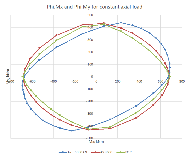
It should be noted that all calculations assumed a rectangular stress block to the AS 3600 code. Use of a parabolic linear stress block would result in further significant reductions in the design moment capacity when the concrete compression zone was triangular.

Where are you based Doug?
On Thu, 21 Nov 2019 at 14:01, Newton Excel Bach, not (just) an Excel Blog wrote:
> dougaj4 posted: “The reinforced concrete biaxial bending spreadsheet has > now been updated: Stress block and capacity reduction factors updated for > AS 3600-2018 ACI factors for US customary units used when stress is entered > in ksi or psi units Example data updat” >
LikeLike
Hornsby, about 45 mins N of central Sydney
LikeLike
Thank you for the post. As someone who is studying section analysis through Excel VBA, I find your content to be the most helpful reference so far.
LikeLike
Doug:
been attempting this myself , If you don’t mind sharing what method are you using to solve for the NA depth and angle for the interaction point?
Method I’ve been trying works well for some configurations but breaks down in the tension side of the P v M curve and with shapes having large aspect ratios.
Also I wasn’t able to get the reinforcement table in the ULS biaxial sheet to work, do you have a post explaining that?
Thanks
LikeLike
ended up trying out a bisection method approach which almost always gets it right but is a fraction slower. Still breaks down in the tension side for unsymmetric reinforcement layouts because the entire interaction surface no longer falls into one of the coordinate quadrants.
If you feel like taking a peek my attempt is here: https://github.com/open-struct-engineer/ConcreteXSection/tree/master/backup_material
LikeLike
Don – for more background on how it works see:
In brief:
For any specified NA angle the section is split into trapezoidal layers parallel to the X axis.
The depth of the NA is found using a closed form solution (but could be found by iteration).
The moment about the X and Y axes is found for that NA location.
That process is repeated with different angles of the NA to find the NA angle that has a resultant angle of the reaction forces in the same direction as the input moments, using Brent’s method.
You will find more details in the link above, and links from that, or try searching the blog, or use the categories drop-down. But if anything isn’t clear, please ask.
What was the problem with the reinforcement table? Each row lists the XY coordinates of the bars at the left and right of each row, then the number of bars and diameter. Also see examples on the Example sheet, that you can copy and paste to the Input sheet.
LikeLike
Thank you for the reply!
Found your paper on the derivations neat stuff, it is interesting seeing different approaches to the problem.
The reinf input, whenever I change anything it seems it breaks something as all of the calculations on the sheet error to N/A(), may be a problem with the version of excel on my work machine will try on my home PC and see if I have better luck.
LikeLike
I recently changed to 64 bit Excel, so that may causing problems. I’ll try it on an older Office and let you know.
LikeLike
Great work, and the program runs so fast ! Can you recommend a book or an article where i can find formulas for creating my own routine for designing bending with biaxial ?
LikeLike
I can’t think of any text books that cover the process in detail. I have seen a few papers with different approaches, I’ll have a look.
Also the VBA code in my spreadsheet is all open source, and my response to DonB in the comments above has more details of my procedure, and a link to an earlier post.
LikeLike
i am trying to create a function to resolve the tension in anchor bolts and compression in concrete under axial load and biaxial bending, i imagine the procedure will be much similar to what is presented here, but the main difference that you don’t limit the concrete strain to 0.003 or maximum steel stress to steel yield strength, so the number of variables will increase to be four:
– The N.A. depth
– The N.A. Angel
– The total tension in the bolts
– The maximum stress in concrete
i can’t find any reference to help me to start, i have done it already for uniaxial bending but with biaxial i am stuck!!
any guidance or references will be appreciated.
LikeLike
This PDF from Bentley gives a great break down of the procedure for base plates:
‘ https://communities.bentley.com/cfs-file/__key/telligent-evolution-components-attachments/01-275894-00-00-00-14-32-79/Biaxial-Analysis-of-General-Shaped-Base-Plates.pdf
LikeLike
DonB – I edited your link because it was automatically downloading the pdf and opening it without any prompt. Seems to work OK now.
LikeLike
Thanks Doug not sure what I may have done wrong there, will be more careful in future comments.
LikeLike
Don – I couldn’t see anything wrong with the link. I suspect it may be another WordPress “improvement”.
LikeLike
Thanks for sharing, in deed it’s a good reference but i have a “silly” question”, in page 4 it’s mentioned that “The next step is to determine the equivalent forces and moments in the local coordinate system for the concrete compression and anchor rods tension.”
What i understand that i have to rotate the section an assumed angle and solve the equations based on the rotated coordinates, however in page 3 it says that “The equivalent force, moment about local x axis and moment about local y axis for a line segment between node i and node i+1” so it got me confused, do i have to keep rotating the section and solve the equation for each face!!.
unfortunately the numerical example skips the important part which is setting the geometry, i understand that this part specially can be done in many different way’s but still it could had helped allot to show an example.
LikeLike
so the general formula for the strain plane is e = c1x+c2y+c3 with c1,c2,c3 being constants. A base assumption in their calculation is that the base plate and anchors are rotated so that the strain and therefore stress would only vary in the y direction this is done to greatly simplify the double integration needed to get the compression resultant force and associated moments.
the calculation on page 3 utilizes line integrals, Green’s Theorem, to calculate the double integral of the stressed area to get the total force. They also reduced the integration further by doing it parametrically for an arbitrary line with two points and a linear varying stress.
LikeLike
I think i will pass on this, i use a method developed by Horn for square base plates with a circular opening which takes into account individual bolts locations to calculate bolts tension and concrete stresses by taking sum of first moment of area for bolts and compression zone and 2nd moment of area for the same about the eccentricity line and the result of dividing the 2nd moment of area over 1st moment of area will be the distance from N.A. to eccentricity line.
it works perfect for a uniaxial eccentricity and converge very fast since you iterate only one variable.
for biaxial eccentricity it seems reasonable to me to rotate the section in an angle equal to ATAN(Mx/My) and calculate the new coordinates (including eccentricity point) by maintaining the N.A horizontal, then solve for also one variable.
a further iteration can be done to iterate the angle of rotation but in most cases it will not be necessary since it’s impact on results is minor in compare to the depth of N.A. and it will not vary much from the first assumed angle.
LikeLike
I also want to share my sheet bi-axial and for shape of a combinations of rectangular sections: for https://www.facebook.com/photo?fbid=10222302066413124&set=gm.1841309899367761
LikeLike
Dl: https://www.mediafire.com/file/hd8g0toi6l5cd00/20210120-General+Section+Design-ACI+Sheet_v1.03.rar/file
Password: SSE
LikeLike
Pingback: Elastic Biaxial Bending | Newton Excel Bach, not (just) an Excel Blog
The enercalc calculation is wrong in the end. Do you agree ?
LikeLike
Sorry for the slow reply.
I wouldn’t say it was “wrong”. Their results are different to mine because they have taken moments about the “plastic centroid”, which is adjusted taken account of the asymmetrical reinforcement, whereas I have used the uncracked concrete centroid. It makes more sense to me to use the concrete centroid, but so long as the applied moments are calculated about the same centroid as the resistance moment the results will still be valid.
If you think their results are wrong in some other way, please let me know.
LikeLike
If you look at Table – 8 Force Column in the document, you will notice some of the values are different when you do a hand calc of stress * Area. The difference is small but I do not know why there is any difference.
For example look at row – 2, Force = (20.47-4.25)*1.27 = 20.5994 kips whereas they have provided 24.16 kips.
LikeLike
Thanks for the details.
Yes, I agree that the numbers as presented are not consistent. It looks like what they have done is to scale down the correction for displaced concrete (Deltaf’c) when the reinforcement in compression is at less than yield stress, so for instance for bar 2:
Force in bar = 20.47 * 1.27 = 26.00 kips
Stress in displaced concrete = -4.25*(20.47/60.00) = -1.45 ksi
Nett force in bar = (20.47-1.45)*1.27 = 24.16 kips
This also works (to 2 decimal places) for all the other bars at less than yield stress.
I don’t know why they didn’t show that calculation in the article, to keep things simple I suppose. Also it is a bit unconservative, because the concrete is treated as being at yield all over the rectangular stress block when calculating the concrete force, so the deduction for area displaced by bars inside the stress block should also use the same stress (-4.25 kPa), which is what my spreadsheet does.
LikeLike
What conditions did you use to iterate ? Did you use theta from -90 deg to +90 deg and c from max-y to min-y ?
LikeLike
For the NA angle the code has limits of +-89 degrees. For the depth of the neutral axis it first checks with the concrete entirely in compression. If that shows that the NA is inside the concrete section it checks each layer working down from the compression face to find the layer with the NA, then uses a closed form solution to find the exact depth.
LikeLike
Thanks!
LikeLike
Just an update, please look at the below link.
https://media.enercalc.com/sel_help_20/toc161394067.htm
This would talk about the ratio that is used in calculating compressive steel force under yield stress. I do not know where can I get the total explanation for the ratio used. Any direction to a text book would be greatly appreciated. Thanks!
LikeLike
I’m not sure which ratio you are talking about here. Do you mean the factor to find the depth of the neutral axis?
LikeLike
See Step 3 Note : “Note, the tensile steel required to balance the compressive steel = As’ (fs’/fy).”
LikeLike
Sorry for the slow reply, I have been busy.
Looking at the linked article the procedure seems to be:
1. Assuming the neutral axis is at the balanced moment level, calculate the stress in compressive steel.
2. Find the area of steel required to increase the bending capacity to the required value.
3. You then need to add tension steel to balance the force in the added compression steel, so that the neutral axis remains at the balanced moment level.
The area of additional tension steel is simply the area of compression steel x compression steel stress / tension steel stress.
And since the tension steel is past the yield point the stress = yield stress.
So additional tensile steel = A’s * f’s/fy
LikeLike
Pingback: Biaxial bending update 2 | Newton Excel Bach, not (just) an Excel Blog
I enjoyed readiing your post
LikeLike
Pingback: ULS Design Functions-biax 0.08 | Newton Excel Bach, not (just) an Excel Blog