
In the course of adding provision for spring end releases to the 3DFrame spreadsheet, I have also tidied up the code for generating the structure stiffness matrix, and added some documentation to the spreadsheet. The revised spreadsheet (version 2.02) can be downloaded from:
3DFrame.zip
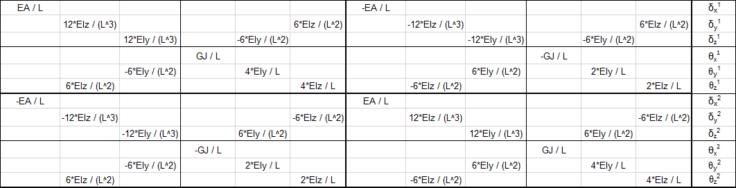
The original version of the spreadsheet, using code from Programming the Finite Element Method, used a beam local axis system with the local x axis aligned with the beam longitudinal axis, the local z axis parallel to the Global ZX plane, and the local y axis completing the right-handed axis system. The beam stiffness matrix consistent with that system is shown below (click the image for a full sized view, or see the “Matrix examples” sheet of the download spreadsheet for a text version):
The Strand7 finite element program uses an alternative system (shown below), and because this program is used to check the results of the spreadsheet I have modified the code to use the same system:
Beam principal axes are defined as i1 to i3, where:
- i3 – is the unit vector directed from Node 1 to Node 2.
- i2 – is the unit vector arising from i2 = Z × i3 where Z is the unit vector in the global Z direction
- i1 – completes the right-handed system such that i1 × i2 = i3
This procedure in effect creates the i2 Axis parallel to the XY plane, and the i1 Axis in the plane parallel to the Z axis; i.e. the Z axis is in effect defined as the vertical axis in the model, and the XY plane is horizontal.
- If the i3 axis is parallel to the Z axis then the i2 axis is parallel to the Y axis in the positive direction.
- Beam principal axes may be rotated about the i3 axis by a specified angle, Gamma.
- Positive rotation is clockwise when looking in the positive i3 direction.
This system is shown in the screen shot below:

In Strand7 the web of I girders is by default aligned with 2 axis, so that the beam flexural stiffness values, I11 and I22, relate to the beam strong and weak axis respectively, as shown below:

The beam local stiffness matrix for this system is shown below:

To combine the beam stiffness matrices into a single global matrix they must all be rotated to a common set of axes, that is the Global XYZ system, using:
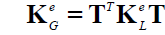
where T is the 12×12 rotation matrix, made up of 4 copies of the 3×3 matrix below:
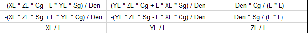
where:
- L is the beam length
- XL, YL, ZL are the components of the local axes in the global system
- Cg, Sg are the Cosine and Sine of Gamma, the angle of the 2 axis to the XY plane
- Den = L * (XL ^ 2 + YL ^ 2) ^ 0.5
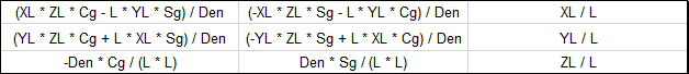
The rotation matrix transpose, TT is:
Application of this method to a single beam is shown in the screen shots below (from the Matrix Examples sheet of the download file).
The local stiffness matrix, KM1:

The rotation matrix, T:

The transpose of the rotation matrix, TT

The matrix CC = KM1.T

The global stiffness matrix KM2 = TT.CC

Alternative beam examples can be generated on the Matrix Examples sheet, by entering a different beam number in Cell C18:

Edit 19 Dec 2016: Formula for Den corrected

Pingback: 3DFrame update | Newton Excel Bach, not (just) an Excel Blog
Pingback: Using the Frame Analysis Spreadsheets | Newton Excel Bach, not (just) an Excel Blog
Dear Sir good day.
The tool / program is something I was looking into for some time. Being the engineer and the structural strength and the VBA enthusiast I found it very useful, especially for smaller – localized problems such as ships structures (grillage calculations), and where the springs can be defined. I have been looking into the code and tried to extract the parts to form the global stiffness matrix, and to write it on the spreadsheet – as noted on the sheet Matrix examples, but could not succeed to do so. Can you please assist me in that respect (assembling and writing down of the global stiffness matrix to the spread sheet with notation within the code) since it would be beneficial for learning purposes and to better understand the code itself. Thank you in advance and
Best regards
Frano
LikeLike
I will do a new post in a few days with more details, but in brief:
The main routine for the frame analysis is p44 in the mFrameP44 module.
This calls routines rigid_jointed3 or spring_jointed3 for each member, which are then assembled into the global matrix with the formkv routine.
There is also a function rigid_jointed3TT which is called from the spreadsheet on the “Matrix examples” sheet.
LikeLike
Hi,
your blog is amazing and contains tons of helpful information. I’m trying to make a solver using 7DOFs frame elements in all three dimensions but I’m stuck on the transformation. My element stiffness matrix is basically the same as yours except mine has an extra DOF for warping, hence the matrix is 14×14 instead of 12×12. How can I approach solving this issue? Do I need to transform the warping?
Thanks in advance.
LikeLike
Pingback: Stepping through 3DFrame | Newton Excel Bach, not (just) an Excel Blog
Pingback: 3D Frame with zero stiffness hinges | Newton Excel Bach, not (just) an Excel Blog
Hi,
your blog is amazing and contains tons of helpful information. I’m trying to make a solver using 7DOFs frame elements in all three dimensions but I’m stuck on the transformation. My element stiffness matrix is basically the same as yours except mine has an extra DOF for warping, hence the matrix is 14×14 instead of 12×12. How can I approach solving this issue? Do I need to transform the warping?
Thanks in advance.
LikeLike
Have a look at:
https://newtonexcelbach.com/2023/08/26/mastan2/
That has links to the Mastan program and also the associated text book (pdf version available for free download).
I have not yet posted the VBA version of my code including warping, because I have been concentrating on the Python version. I will look at uploading the VBA version (after doing some checks), but it’s worth looking at the posts related to the Python version for more background information and also open-source code. See the latest post at:
https://newtonexcelbach.com/2023/09/03/3dframe-py-update/
LikeLike
Thank you, now I have enough materials to study. But I must say, it does not look like there exist an easy solution for 7DOFs local->global transformation…
By the way, I have a 7DOF’s element stiffness matrix and geometric matrix that include the effects of:
I looked into your Python stiffness calculations and didn’t see that. Hit me if you want to have them.
Sorry for my English.
LikeLike