
Following the first post in this series, this post compares friction losses in prestressing cables as defined in the Australian Concrete Structures Code (AS 3600), compared with a cable modelled with contact elements in Strand7. The example used is based on the same three span beam used in the previous post (taken from the book Concrete Structures by Warner, Rangan, Hall and Faulkes), but the cable profile has been modified over the internal supports to provide a more realistic profile:

In the Strand7 analyses the prestress was applied by applying a strain preload to additional elements at each end of the cable, representing the stressing jacks. The strain was adjusted to generate a force of 1500 kN at each end of the cable.
Friction in AS 3600 is defined by:


As in the previous post, the friction curvature coefficient was taken as 0.2, and the wobble factor as 0.016.
In Strand7 the frictional behaviour of the contact elements is controlled by two factors:
- The friction coefficient
- The “sticking friction stiffness”: For Zero Gap and Normal Gap elements with non-zero coefficients of friction, the Sticking Friction Stiffness provides the lateral elastic connection between nodes until the point where the element slips in the lateral (frictional) direction; while the frictional force is below the current frictional capacity the lateral elastic stiffness is added.
There is little guidance on how the Strand7 sticking friction stiffness should be determined, and as far as I know, no guidance on how it relates to the AS 3600 “wobble factor”. A range of values have therefore been used, and the results of the Strand7 FEA and the AS 3600 formula compared.
The friction factor was initially varied between 0.2 and 0.3, with a constant sticking friction stiffness of 10,000 kN/m. The resulting tendon forces from one end to mid-length are shown below:
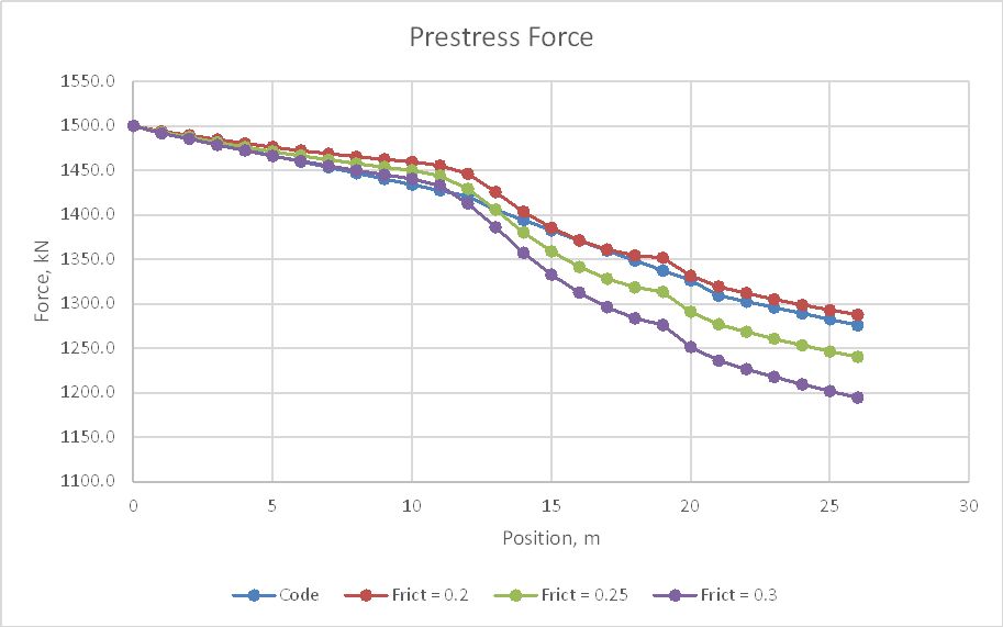
Over the first ten metres, where the cable profile had a low curvature, the AS 3600 formula gave slightly higher friction losses than the FEA with 0.3 friction factor, but over the remainder of the length all FEA results had higher friction losses and the friction factor of 0.2 was the best overall fit.
The analysis was then run with a friction factor of 0.2, and sticking friction stiffness values of 10,000 kN/m, 1000 kN/m, and 100 kN/m. The AS 3600 formula was checked with a wobble factor of 0.016 (Code 1) and 0.0 (Code 2):
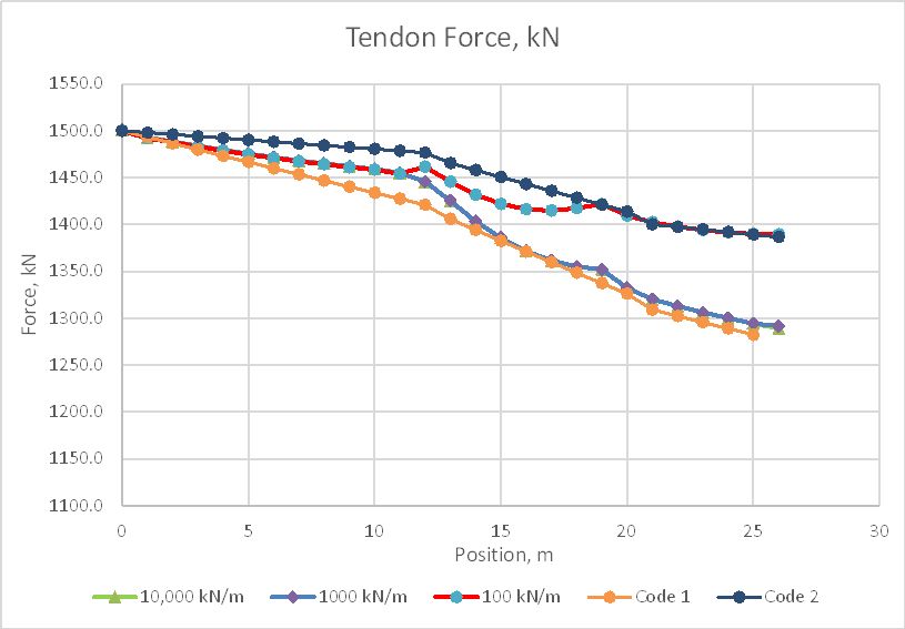
All three of the FEA results are very close, up to 11.0 metres, where the 100 kN/m diverges to meet the Code 2 line. The other two lines remain very close over the full length, and are a good match with the Code 1 line from 14 metres onwards.
The above analyses were continued by reducing the strain in the jack elements by 5%, resulting in approximately 8 mm shortening of the elements, representing the loss of jack force due to lock off of the strands. In the graph below line 4a is the 10,000 kN/m line without the reduction in prestress:

Now all three runs with different sticking friction values have significantly different results over the full length. The effect of these differences on the bending moments in the beam will be examined in the next post in this series.

Another beautiful blogpost, looking on to study in detail.
LikeLike