
The Conjugate Beam Method is a variation of the Moment-Area Method that allows beam slopes and deflections to be calculated purely from the calculation of shear forces and bending moments of the beam with (in some cases) modified support conditions. Both methods were developed by Christian Otto Mohr, although the Conjugate Beam Method is often attributed to others. I will have a closer look at the history in a later post, but in this post I will look at how it works, with a simple Excel based example.
The basis of the method is:
- Calculate the bending moment diagram for the real beam with the actual support conditions.
- Apply the bending moment diagram divided by EI to the “conjugate beam”, as a distributed load. The conjugate beam is an imaginary beam of the same length, with support conditions modified as described below. (E = elastic modulus; I = second moment of area. Note that both may vary along the length of the beam).
- Calculate the shear force and bending moment diagram for the conjugate beam. At any cross section the numerical value of the shear force is then equal to the slope of the real beam, and the bending moment is equal to the deflection of the real beam.
The changes to the support conditions in the conjugate beam are based on the following requirements:
- At any point where the deflection is zero the conjugate beam moment must be zero, requiring either a simple end support or free end, or an internal hinge.
- Where the end slope is zero the conjugate beam shear must be zero, requiring a free end.
- Similarly, where the deflection or slope is non-zero the conjugate beam must be able to generate a moment or shear force.
- Where there is a discontinuity in the slope (at an internal hinge) the conjugate beam must have a simple support.
These modifications to the support conditions are illustrated below (from the Wikipedia Article):

The spreadsheet ConjugateBeam.zip provides a simple example of the method applied to a simply supported beam with two point loads:

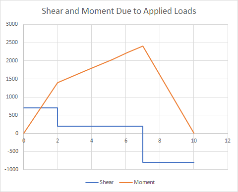
The shear and moment diagrams are calculated for the specified load positions and values, using the usual methods (Columns B and C above):
The bending moment due to the applied load is then divided by EI to give the applied load for the conjugate beam. For a simply supported beam the conjugate beam supports are unchanged, but we need to calculate the reaction force at the supports. A convenient way to do that is to treat the conjugate beam as a cantilever fixed at End 2, and calculate the shear and moment at End 2 (Columns E and F). The End 1 shear force for the simply supported beam is then minus this moment, divided by the beam length, and this force is applied along the full length of the beam(Column G and below):
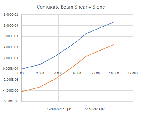
The conjugate beam bending moment diagram is now found for the simply supported shear diagram (Column H and below):

Note that the bending moment at End 2 is exactly zero, as would be expected. The numerical values of the conjugate beam shear and bending moment are equal to the slope and displacement of the original beam.
An alternative calculation of the shear force at End 1 of the conjugate beam is shown below; taking moments about End 1, to find the reaction at End 2, and hence the End 1 force. In both cases the calculation is equivalent to calculating the deflection at the end of a cantilever, and dividing by the beam length to find the rotation required to return the beam to horizontal.

In general the maximum deflection of the beam will be intermediate between the two applied loads. The Excel solver has been set up in the spreadsheet to find this location by adjusting the value in cell A18 so that the conjugate beam shear (equal to the original beam slope) is equal to zero. This is the point of maximum bending moment in the conjugate beam, and maximum deflection in the original beam:
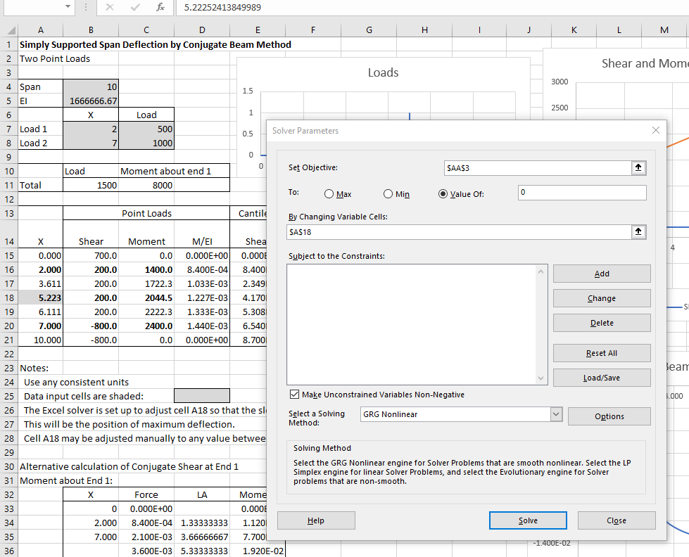
To run the solver, select the Data tab, click the solver icon (extreme right), then click solve. If the solver icon does not display the solver must be installed from the File-Options-Add ins menu.

Oh what a delight on a Friday morning. Dont think I have heard mention of conjugate beams since I was a student.
Tweeted a link to this one. Bill
LikeLike
Thanks Bill.
I meant to mention that this topic was prompted by a discussion at Eng-Tips:
http://www.eng-tips.com/viewthread.cfm?qid=419388
LikeLike
Pingback: Year 10 Report | Newton Excel Bach, not (just) an Excel Blog
Hi Doug, This is a great explanation! The excel looks great and would really help me out. I see the link to the spreadsheet is down. Is there any chance you could send me a copy?
Cheers
Blair
LikeLike
I had to change all my download links to keep Google happy, which means a lot of the old ones no longer work.
I have updated this one now. Please let me know if any problems.
LikeLike
Thanks, it works great!
LikeLike