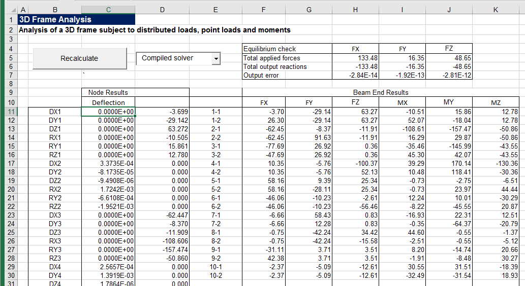
In the course of adding provision for spring end releases to the 3DFrame spreadsheet, I have also tidied up the code for generating the structure stiffness matrix, and added some documentation to the spreadsheet. The revised spreadsheet (version 2.02) can be downloaded from:
3DFrame.zip
The original version of the spreadsheet, using code from Programming the Finite Element Method, used a beam local axis system with the local x axis aligned with the beam longitudinal axis, the local z axis parallel to the Global ZX plane, and the local y axis completing the right-handed axis system. The beam stiffness matrix consistent with that system is shown below (click the image for a full sized view, or see the “Matrix examples” sheet of the download spreadsheet for a text version):
The Strand7 finite element program uses an alternative system (shown below), and because this program is used to check the results of the spreadsheet I have modified the code to use the same system:
Beam principal axes are defined as i1 to i3, where:
- i3 – is the unit vector directed from Node 1 to Node 2.
- i2 – is the unit vector arising from i2 = Z × i3 where Z is the unit vector in the global Z direction
- i1 – completes the right-handed system such that i1 × i2 = i3
This procedure in effect creates the i2 Axis parallel to the XY plane, and the i1 Axis in the plane parallel to the Z axis; i.e. the Z axis is in effect defined as the vertical axis in the model, and the XY plane is horizontal.
- If the i3 axis is parallel to the Z axis then the i2 axis is parallel to the Y axis in the positive direction.
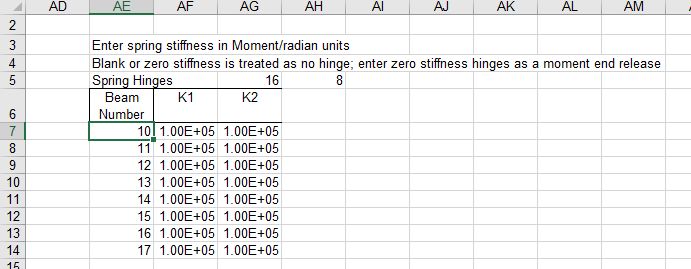
- Beam principal axes may be rotated about the i3 axis by a specified angle, Gamma.
- Positive rotation is clockwise when looking in the positive i3 direction.
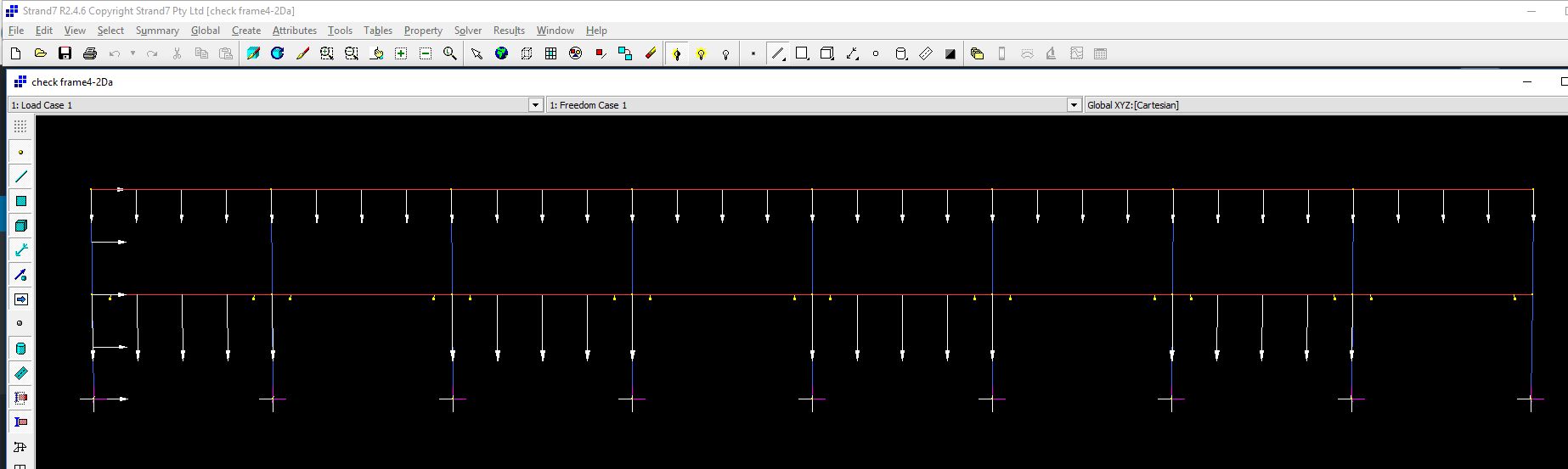
This system is shown in the screen shot below:

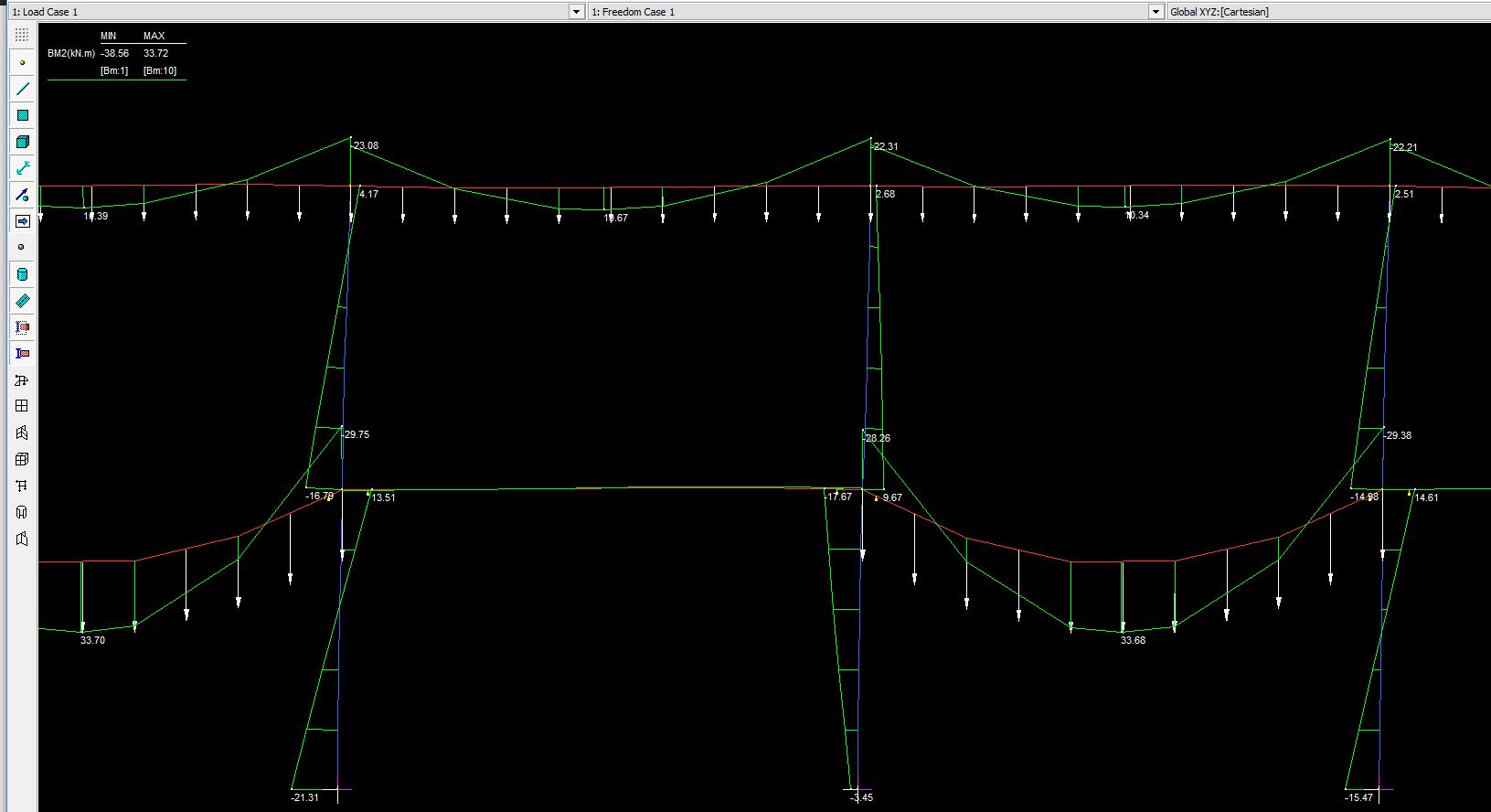
In Strand7 the web of I girders is by default aligned with 2 axis, so that the beam flexural stiffness values, I11 and I22, relate to the beam strong and weak axis respectively, as shown below:

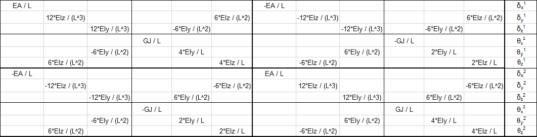
The beam local stiffness matrix for this system is shown below:

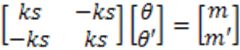
To combine the beam stiffness matrices into a single global matrix they must all be rotated to a common set of axes, that is the Global XYZ system, using:
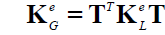
where T is the 12×12 rotation matrix, made up of 4 copies of the 3×3 matrix below:
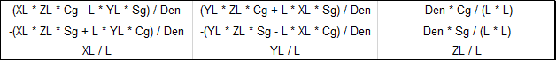
where:
- L is the beam length
- XL, YL, ZL are the components of the local axes in the global system
- Cg, Sg are the Cosine and Sine of Gamma, the angle of the 2 axis to the XY plane
- Den = L * (XL ^ 2 + YL ^ 2) ^ 0.5
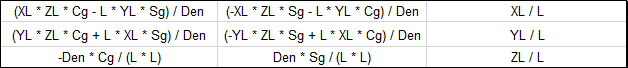
The rotation matrix transpose, TT is:
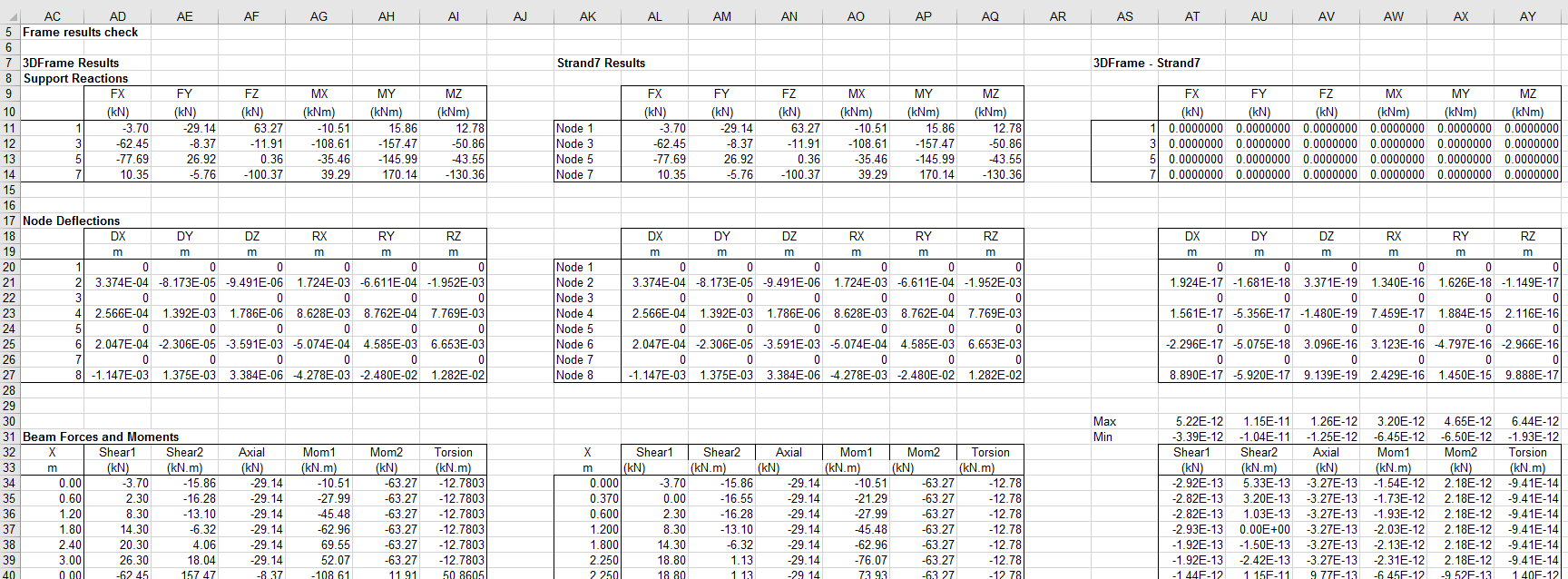
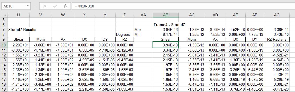
Application of this method to a single beam is shown in the screen shots below (from the Matrix Examples sheet of the download file).
The local stiffness matrix, KM1:

The rotation matrix, T:

The transpose of the rotation matrix, TT

The matrix CC = KM1.T

The global stiffness matrix KM2 = TT.CC

Alternative beam examples can be generated on the Matrix Examples sheet, by entering a different beam number in Cell C18:

Edit 19 Dec 2016: Formula for Den corrected