
The two main Australian Standards covering prestressed concrete structures (AS 3600, Concrete Structures, and AS 5100 Part 5, Concrete Bridges) put a limit on the allowable increase in stress in reinforcement and prestressing strands and tendons, when the load increases from the moment that results in zero stress at the tensile concrete face to the maximum moment under Serviceability Limit State loads.
The current versions of my beam design spreadsheets do not directly provide the value of this stress increment, but it is easy to calculate, using the Excel Goal Seek function.
The examples below can be downloaded from:
Composite Design Functions-Stress Inc.zip
The screen shots below show an example using the Beam Design Functions spreadsheet, with a standard pre-tensioned “Super-T” bridge beam:
To find the reinforcement stresses when the stress at the bottom concrete face is zero, open the Goal Seek dialog (under the Data tab) and enter:
- Set cell = C10 (Depth of Neutral Axis)
- To value = 1800 (Overall depth of the section)
- By changing cell = A6 (Applied Moment)
Click OK, then OK again when Goal Seek has found the moment (in cell A6) that results in a Neutral Axis depth of 1800 mm (in cell C10):
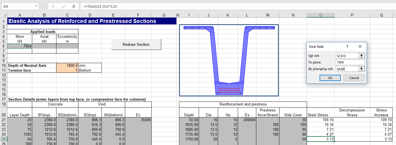
The resulting reinforcement stresses are found on the “Elastic 1 Out” sheet, in Column C (for the top and bottom layers) and Column L (for all layers). This data can be displayed on the “Elastic1 Input” sheet with a simple formula: =’Elastic1 Out’!L13. Only the value for the bottom layer is required, but the screen shot above shows the results for all steel layers in Column O. When the Goal Seek process is complete the steel stress(es) in Column O should be copied to Column P, using Copy and Paste-Special-As Values. In Column Q add a formula for the difference between Columns O and P: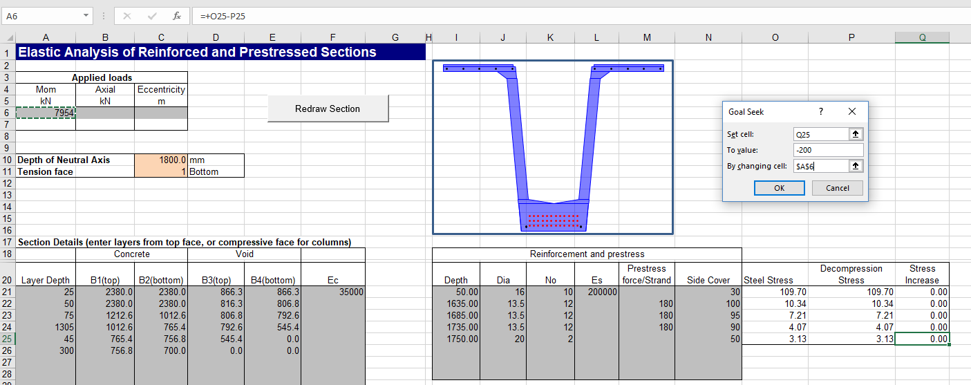
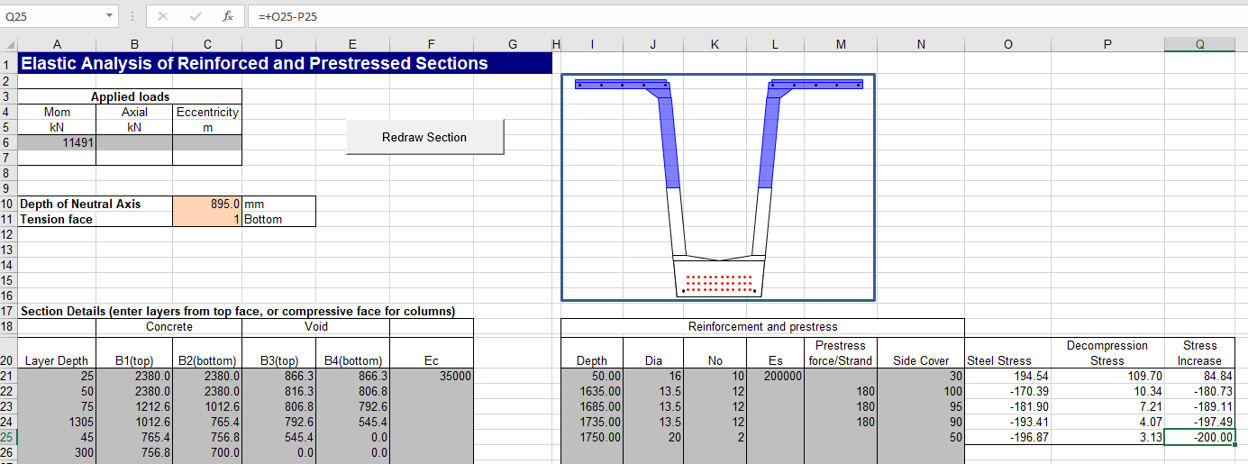
The stress change for any applied bending moment can then be found simply by entering the required moment in Cell A6. Alternatively, Goal Seek can be used to find the bending moment that will result in the maximum allowable stress increase:
- Set cell = Q25 (Stress Increase for the bottom layer)
- To value = -200 (or the specified stress in MPa, tension negative)
- By changing cell = A6 (Applied Moment)
Super-T beams are of course usually used in composite construction, with a reinforced concrete top slab. The process described above can also be carried out on a composite section using the Composite Design Functions spreadsheet, with the following changes:
- The composite output does not currently have a full list of stresses in each layer, so use the stress in the bottom layer (and top if desired) from column C, Stage 2 results. We are interested in the stress in the bottom layer of the precast, so the required value is in cell =’ElasticComp Out’!C33 ( Stage 1 Bottom Steel).
- To find the moment for zero stress at the bottom face, the value in cell D13 (Combined Depth NA, Stage 2) must be set to the depth of the composite section (2000 mm in the example) with Goal Seek, by adjusting cell B7:


The reinforcement stress at this bending moment is copied and pasted as value to cell Q27: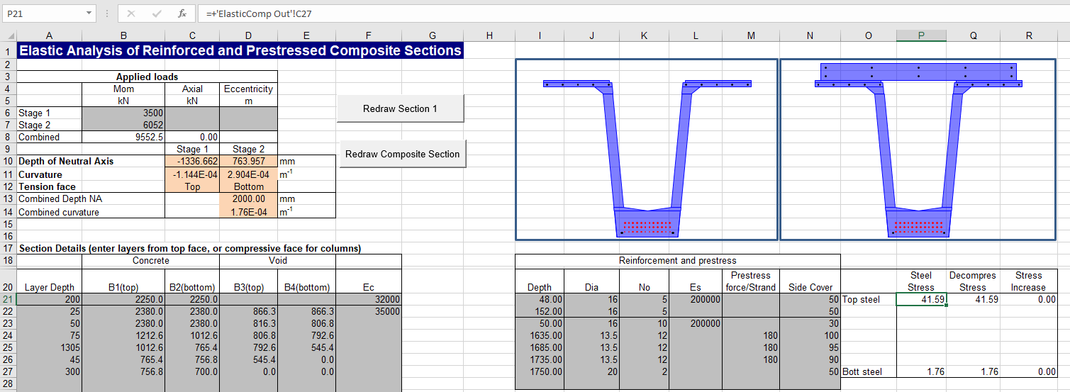
The stress increase, in cell R27, is then adjusted with Goal Seek to -200 (or the required value), by again adjusting the Stage 2 bending moment in cell B7.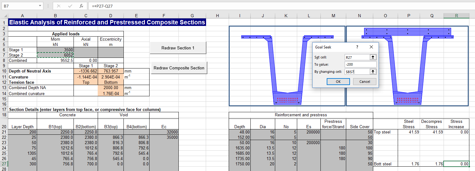
The total maximum SLS applied bending moment is then given in cell B8, being the sum of the moment applied to the precast only, plus the maximum additional load on the composite section: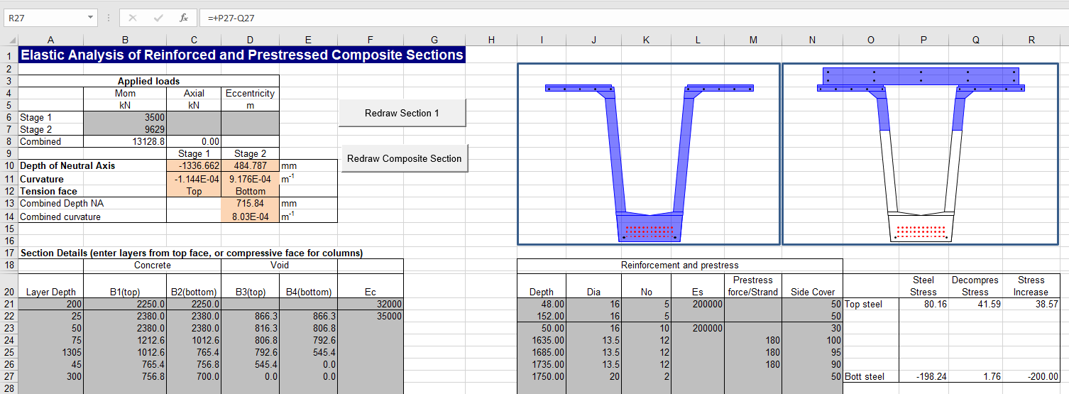
The output sheet gives additional details of stresses, strains, forces and moments, as well as a strain diagram for loads on the precast and composite sections: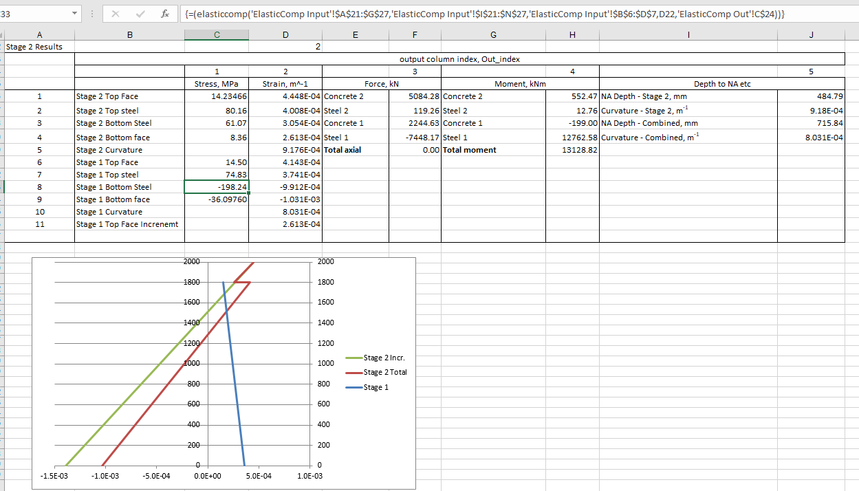

Pingback: #Excel Super Links #87 – shared by David Hager | Excel For You
Pingback: Composite Beam Spreadsheet Update 1.01 | Newton Excel Bach, not (just) an Excel Blog