Using RC Design Functions – 2

In the previous post we looked at a summary of the functions in the RC Design Functions spreadsheet, and ways of using the EStress function (download file with examples).  In this post we will look in more detail at the output from EStress.

Since the last post there have been some minor changes to the EStress output, and the calculation of cracking moment including shrinkage effects has been updated to the latest version of the code, so to follow the notes below it is best to download the latest version of RC Design Functions.

The output is controlled by the arguments out1 and out2:

EStress function arguments

EStress function arguments

The “Insert Function” dialog can be displayed by clicking on the icon to the left of the Edit Bar, and selecting the function from the “User Defined” category, or enter “=Estress(” then click the Insert Function icon. Out1 selects the output column, and Out2 the output row.

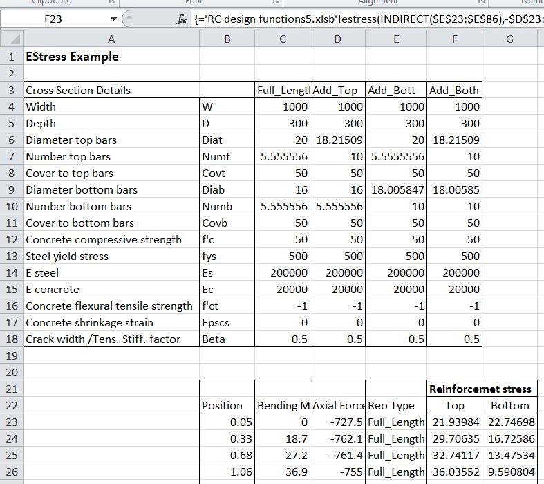
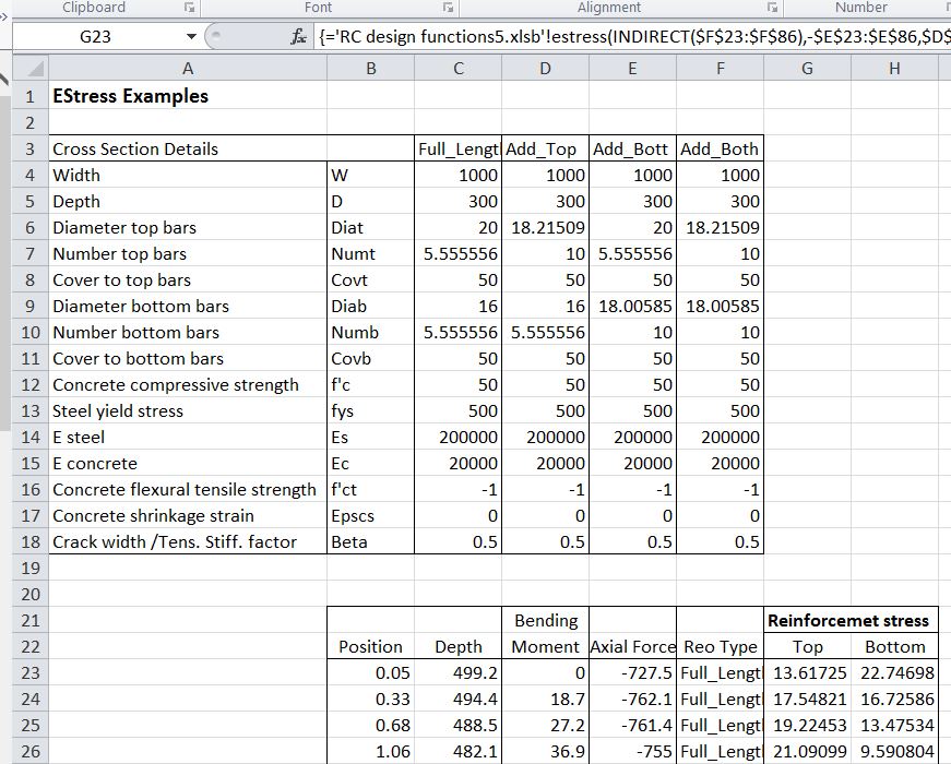
Out1 = 1 returns stress values (in MPa) and Out1 = 2 returns strain and curvature (in m^-1) results:
RCdesign5b-1

The stress and strain results are given at (controlled by the value of Out2):

  1. Concrete top face
  2. Top steel centroid
  3. Bottom steel centroid
  4. Bottom face

Note that if the concrete is in tension (negative strain) the stress displays as zero, because the analysis ignores tensile stress in the concrete.

If the Code argument is omitted, or is equal to 1 or 2, row 5 of the stress output returns the maximum allowable stress under SLS loading according to the Australian design codes, (AS 3600 and AS 5100).  If the Code value is 2, row 6 returns the maximum allowable stress under SLS dead load only, according to AS 5100 (the bridge design code).

The strains and curvature returned in column 2 are calculated assuming zero tension stress in the concrete.

Out1 = 3 or 4 returns force and moment results:

RCdesign5b-2

The total force and moment should be equal to the input applied load values.  The force and moment in the concrete are calculated from the total section area above the neutral axis times the average concrete stress (compression face stress / 2), less the concrete force and moment over the area of the reinforcement in the compression zone (if any).

Out1 = 5 or 6 returns the depth to the neutral axis and cracking stresses and moments; and an echo of the input values respectively:

RCdesign5b-3

The concrete design flexural tensile strength (rows 4 and 7) is based on the code provisions if f’ct is specified as -1 in the input, or the input value for any other value.

The AS 3600 cracking moment including shrinkage is based on Cl. 8.5.3.1 of the code and the input shrinkage strain:

AS 3600 Cl 8.5.3.1 (part)

AS 3600 Cl 8.5.3.1 (part)

The other code cracking moments do not allow for shrinkage.

The values in output Column 6 should be equal to the corresponding input values.  Any difference indicates that the input ranges have not been specified correctly.

Out1 = 7 returns miscellaneous intermediate results:
RCdesign5b-4

1, 2:  Area of tension and compression steel.
3,4:  Depth of the centroid of the tension and compression steel, measured from the compression face.
5,6: Maximum compressive load and associated bending moment.
7,8: Maximum tensile load and associated bending moment.
9:    Sign of the applied moment (tension on the bottom face positive)
10:  Ig, the second moment of area of the gross  section, including reinforcement using transformed area properties.

The maximum compressive an tensile loads are based on the specified concrete compressive strength and steel tensile strength respectively.  Note that no reduction factors are applied, and the calculated stresses and strains in output columns 1 and 2 assume elastic behaviour under all loads.

Out1 = 8 returns crack width and effective stiffness results:

RCdesign5b-5

If the input Code value = 4 or 5 then Out1 = 8 returns just the crack width to the British code BS 5400.  The Mq/Md  ratio (Live Load/ Dead Load) is set to the input Beta value.

For a Code value of 3 (Eurocode 2) Out1 = 8 returns:

Out2
<2:   Crack width for kt = Out2-1 (kt = 0.4 for long term load, 0.6 for short term)
2:      Crack spacing
3:      Curvature with no tension stiffening
4:       Curvature to Eurocode 2, with no shrinkage
5:        Shrinkage curvature to Eurocode 2
6:        Total curvature to Eurocode 2
7:        Uncracked curvature; = 0.0 for cracked section
8:       Effective E, based on total curvature to Eurocode 2 and Ig

Posted in Concrete, Excel, Newton, UDFs, VBA | Tagged , , , , , | 1 Comment

A Fish Called Newton

From Big Questions Online (via Letters to Nature):

By Frank Wilczek

    April 22, 2013

Imagine a planet encrusted with ice, beneath which a vast ocean lies. (Imagine Europa.)

Within that ocean a species of brilliant fish evolved. Those fish were so intelligent that they took up physics, and formulated the laws that govern motion. At first they derived quite complicated laws, because the motion of bodies within water is complicated.
One day, however, a genius among fish, call her Fish Newton, had a startling new idea. She proposed fundamental laws of motion––Newton’s laws––that are simpler and more beautiful than the laws the fish had derived directly from experience. She demonstrated mathematically that you could reproduce the observed motions from the new, simpler laws, if you assume that there is a space-filling medium that complicates things. She called it Ocean.

Read the full article at Big Questions Online

This is the clearest statement I have seen (at least from a recognised scientist in the field) that “space” is full of matter, albeit a different form of matter to the one we are familiar with.  It makes me wonder how much the underlying mental picture of what space consists of affects the interpretation of the observational evidence and the maths by different scientists.  I suspect that it may be more than they would like to think.

Posted in Newton | Tagged , , | Leave a comment

While sitting in a tin can …

… astronaut Chris Hadfield has created a video cover of David Bowie’s “Space Oddity” made on location in the International Space Station:

and a damned good job he made of it too.

Update 7th Aug 2014: The original video went private, now updated with a new link

Top comment:

I can’t stop watching this. Seriously.. everything is surreal in this video. No special effects or CGI gimmicks. The earth in the background is really us.. our home. This is just a fine example of humanity at it’s best. A reminder of the things we can achieve and experience when we work together for a better life instead of killing/taking advantage of one another.

And more details about how the piece was put together:

ISS Commander Chris Hadfield Plays A Canadian Larrivée Guitar On Space Oddity

Posted in Bach, Newton | Tagged , , , | Leave a comment

Using RC Design Functions – 1

Download RC Design Functions (includes full open source code) and EStress Examples.xlsx

This series of posts will cover ways of using the many functions contained in the RC Design Functions spreadsheet, starting with some general comments on using the User Defined Functions (UDFs), and details of usage of the Estress function.

All the functions available in the spreadsheet are listed on the Contents sheet:

RCdesign5a-1

Reinforced Concrete Section Analysis Functions

RCdesign5a-2

Time related properties and associated functions

There are also over 40 general purpose and utility functions called by the main functions listed above, most of which can also be used as UDFs from the spreadsheet.

The simplest way to use the functions is to enter data in the grey cells on the function input sheet.  For instance for Estress: RCdesign5a-3
The resulting 8 columns of output can then be seen on the results sheet:
RCdesign5a-4

RCdesign5a-5
The results are generated using the UDF EStress:
EStress(Input Range, Axial Load, Moment, Output Column Index, Output Row Index, Prestress, Code, Depth, Ect, Cracked):

  • Input Range: Single column range, 15 rows as shown in range D3:D17 in the screen-shot above.
  • Axial Load, Moment: Design actions; see notes
  • Output Column Index, Output Row Index: Index values defining output as shown in screen-shots above
  • Prestress: Single column, two row range with prestress in top and bottom row reinforcement (MPA)
  •  Code: Design code for crack width calculation; see notes
  • Depth: Section depth; overriding value in input range 
  • Ect: Concrete elastic modulus;  overriding value in input range 
  • Cracked: See Note 12

Notes:

  1. The functions assume a rectangular concrete section, or T section with the neutral axis within the flange.
  2. Typical output is shown on the Estress Out sheet (screen shots above).
  3. Input ranges must be a single column range, with data ordered as shown above
  4. “Axial load” may be a single value or cell, or a multi cell range, or an array of values
  5. If “axial load” is a range or an array then the function will return a single column array with one value for each axial load.
  6. If “moment” and/or “depth” ranges are specified they must have the same number of values as “axial load”.
  7. If a “depth” range is specified the depth corresponding to each moment and axial load supersedes the value specified in the input range.
  8. Display of output values is controlled by the output indices, as shown in the examples.
  9. The optional “code” parameter only affects crack width and curvature output (out1 = 8); Available Codes are:
    1: AS3600
    2: AS5100
    3: EC2
    4: BS5400
    5: BS8100
    6: CEB_FIP
  10. If the “Ect” parameter is specified this supersedes  the Elastic Modulus value specified in the input range.
  11. The input assumes a “top” and “bottom” face with positive bending tending to cause tension in the bottom face.
  12. If the “Cracked” parameter is specified as True (or 1) the concrete is treated as cracked for curvature calculations under all load conditions. The default value is Cracked = False.

The main advantage in writing the routines in this spreadsheet as UDFs is that it offers much more flexibility in use.  The section data range, and the list of axial loads and bending moments may be located anywhere, in any open spreadsheet, and similarly the output data can be located in any convenient range.  As an example, the screenshot below shows bending moment and axial load data for a concrete arch structure, together with the associated stress in the top and bottom reinforcement layers.

EStress input and results

EStress input and results

The UDF, EStress, is located in a different workbook to the data, so it must be preceded by the file name. The easiest way to do this is to use the “Insert Function” icon to the left of the edit bar:

Insert Function

Insert Function

The Estress function may then be selected from the User Defined category. The full input for the top reinforcement stress is:

=’RC design functions6.xlsb’!estress($C$4:$C$18,-D23,C23,1,2)

The axial load in D23 is specified as compression negative, whereas EStress treats compression as positive; the cell D23 is therefore preceded with a minus. C23 is the bending moment, and the final two inputs specify stress output (1), and the top steel layer (2).

The same function is used for the bottom reinforcement stress, with the final 2 replaced with a 3.  Note that the section data is entered as an “absolute” address (with $ signs), so that it does not change when the function is copied.

Having entered the functions for the top and bottom steel stress, and copied down over the full list of results, the results may be plotted as shown below:

Reinforcement stresses around arch structure

Reinforcement stresses around arch structure

On the next sheet the example shows how  reinforcement that varies along the length of the arch can be dealt with.  The reinforcement is defined in the four columns: C4:F18. The four columns are named: Full_Length, Add_Top, Add_Bott, Add_Both.

EStress input and results

EStress input and results

The Indirect function is used to select the appropriate data, as specified in the range E23:E86:

=’RC design functions6.xlsb’!estress(INDIRECT(E23:E86),-D23:D86,C23:C86,1,2)

In this case the function has been entered as an array function, with the full list of axial forces (D23:D86), bending moments (C23:C86), and reinforcement types (E23:E86), rather than just the top cell.  The function returns values for all 64 rows of the input ranges, and must be entered as an array function (press Ctrl-Shift-Enter; see Using Array Formulas for details).

The resulting graph is shown below; note the reduced stress in the regions with additional reinforcement.

Reinforcement stresses around arch structure

Reinforcement stresses around arch structure

The third example illustrate how a section with varying depth can be analysed, without entering the full section details for every cross section. In the screen-shot below the section depth has been added in Column C:

RCdesign5a-14
The full function is now:

=’RC design functions6.xlsb’!estress(INDIRECT(F23:F86),-E23:E86,D23:D86,1,2,,,C23:C86)

The range C23:C86 specifies the section depth (in mm), and this overrides the value specified in the section data range.  The function again must be entered as an array function.

The examples shown above may be downloaded from EStress Examples.xlsx. Note that the file RC Design Functions6.xlsb should be in the same folder as the examples file, and should be opened first.  Estress Examples.xlsx should then be opened, and will link to the RC Design Functions automatically.

Posted in Beam Bending, Concrete, Excel, Newton, UDFs, VBA | Tagged , , , , , | 13 Comments

World’s Largest Natural Arches

Update 9th May 2013: Not in the top 10 for size, but a little known rock formation in Australia:

Kissing Rocks

From AmusingPlanet.com and The Natural Arch and Bridge Society

A natural arch is a geological formation where rocky cliffs subject to erosion from the sea, rivers or weathering forms a rock arch. Some natural arch has a stream of water flowing underneath, in which case the arch is called a natural bridge. The distinction between a bridge and arch is somewhat arbitrary. The Natural Arch and Bridge Society identifies a bridge as a subtype of arch that is primarily water-formed. By contrast, the Dictionary of Geological Terms defines a natural bridge as a “natural arch that spans a valley of erosion.” The correct method to measure an arch is also debated because of which the reported measurements often varies from source to source. Under these circumstances to prepare an irrefutable list of the world’s largest or longest or highest natural arch is impossible. Amidst this confusion new discoveries and potential candidates always keep popping up around the globe.

Natural arches are abundant in the deserts of Utah and Arizona in the United States. The Arches National Park in eastern Utah contains the largest concentration of significant natural arches in the world. As many as 2000 natural sandstone arches, including the world-famous Delicate Arch, in addition to a variety of unique geological resources and formations are found in this region.

See AmusingPlanet.com for more photos and details of the 10 biggest natural arches from around the world according to the Natural Arch and Bridge Society

Posted in Arch structures, Newton | Tagged , | 1 Comment