Download RC Design Functions (includes full open source code) and EStress Examples.xlsx
This series of posts will cover ways of using the many functions contained in the RC Design Functions spreadsheet, starting with some general comments on using the User Defined Functions (UDFs), and details of usage of the Estress function.
All the functions available in the spreadsheet are listed on the Contents sheet:
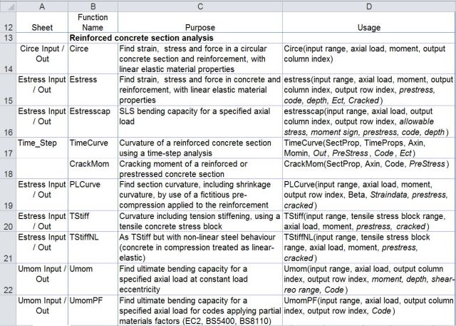
Reinforced Concrete Section Analysis Functions

Time related properties and associated functions
There are also over 40 general purpose and utility functions called by the main functions listed above, most of which can also be used as UDFs from the spreadsheet.
The simplest way to use the functions is to enter data in the grey cells on the function input sheet. For instance for Estress: 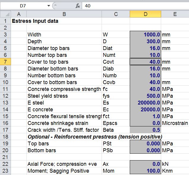
The resulting 8 columns of output can then be seen on the results sheet:
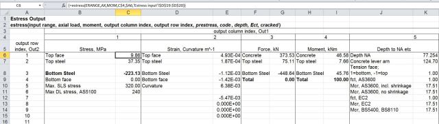
The results are generated using the UDF EStress:
EStress(Input Range, Axial Load, Moment, Output Column Index, Output Row Index, Prestress, Code, Depth, Ect, Cracked):
Notes:
- The functions assume a rectangular concrete section, or T section with the neutral axis within the flange.
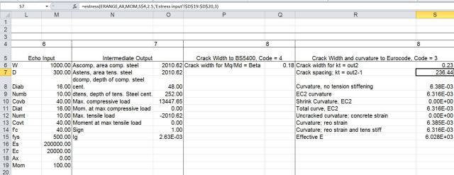
- Typical output is shown on the Estress Out sheet (screen shots above).
- Input ranges must be a single column range, with data ordered as shown above
- “Axial load” may be a single value or cell, or a multi cell range, or an array of values
- If “axial load” is a range or an array then the function will return a single column array with one value for each axial load.
- If “moment” and/or “depth” ranges are specified they must have the same number of values as “axial load”.
- If a “depth” range is specified the depth corresponding to each moment and axial load supersedes the value specified in the input range.
- Display of output values is controlled by the output indices, as shown in the examples.
- The optional “code” parameter only affects crack width and curvature output (out1 = 8); Available Codes are:
1: AS3600
2: AS5100
3: EC2
4: BS5400
5: BS8100
6: CEB_FIP
- If the “Ect” parameter is specified this supersedes the Elastic Modulus value specified in the input range.
- The input assumes a “top” and “bottom” face with positive bending tending to cause tension in the bottom face.
- If the “Cracked” parameter is specified as True (or 1) the concrete is treated as cracked for curvature calculations under all load conditions. The default value is Cracked = False.
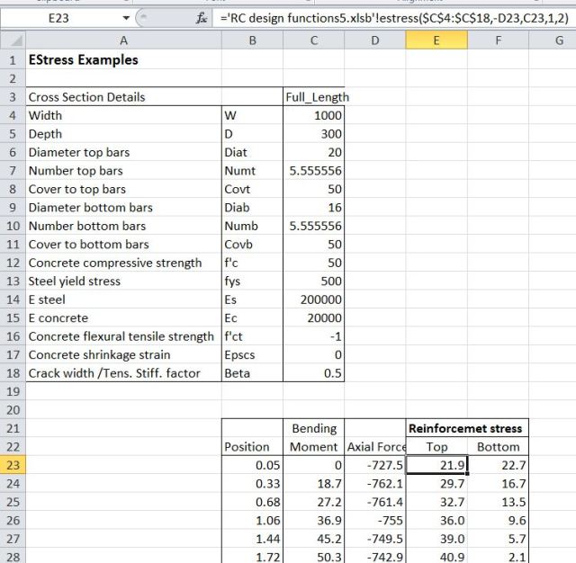
The main advantage in writing the routines in this spreadsheet as UDFs is that it offers much more flexibility in use. The section data range, and the list of axial loads and bending moments may be located anywhere, in any open spreadsheet, and similarly the output data can be located in any convenient range. As an example, the screenshot below shows bending moment and axial load data for a concrete arch structure, together with the associated stress in the top and bottom reinforcement layers.
EStress input and results
The UDF, EStress, is located in a different workbook to the data, so it must be preceded by the file name. The easiest way to do this is to use the “Insert Function” icon to the left of the edit bar:

Insert Function
The Estress function may then be selected from the User Defined category. The full input for the top reinforcement stress is:
=’RC design functions6.xlsb’!estress($C$4:$C$18,-D23,C23,1,2)
The axial load in D23 is specified as compression negative, whereas EStress treats compression as positive; the cell D23 is therefore preceded with a minus. C23 is the bending moment, and the final two inputs specify stress output (1), and the top steel layer (2).
The same function is used for the bottom reinforcement stress, with the final 2 replaced with a 3. Note that the section data is entered as an “absolute” address (with $ signs), so that it does not change when the function is copied.
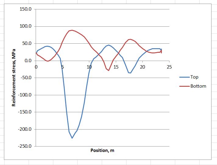
Having entered the functions for the top and bottom steel stress, and copied down over the full list of results, the results may be plotted as shown below:
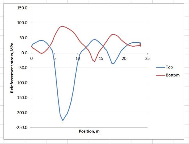
Reinforcement stresses around arch structure
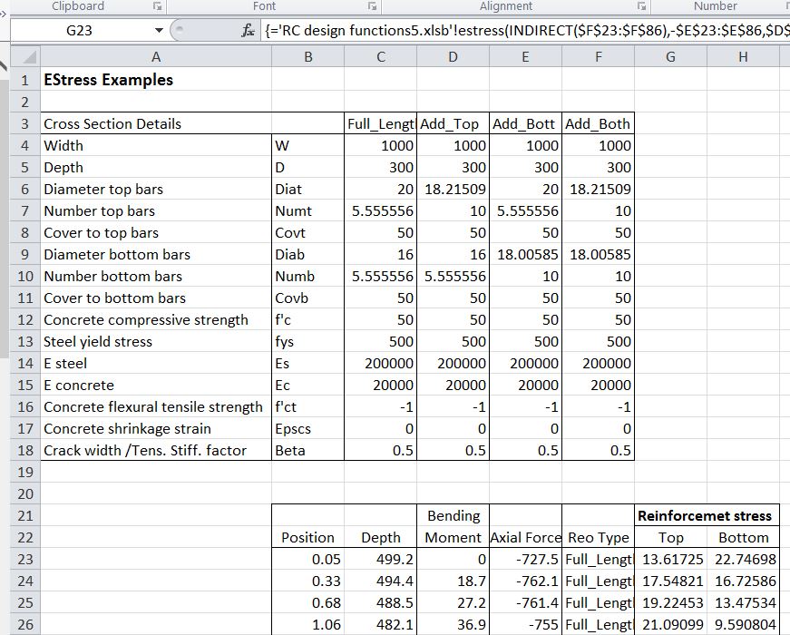
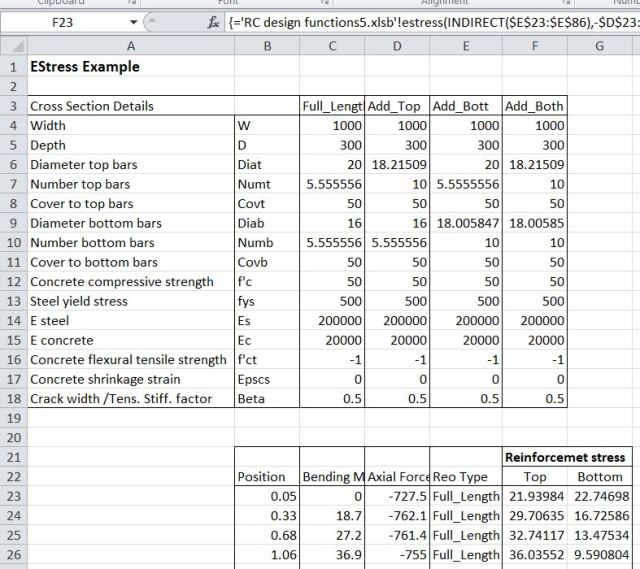
On the next sheet the example shows how reinforcement that varies along the length of the arch can be dealt with. The reinforcement is defined in the four columns: C4:F18. The four columns are named: Full_Length, Add_Top, Add_Bott, Add_Both.
EStress input and results
The Indirect function is used to select the appropriate data, as specified in the range E23:E86:
=’RC design functions6.xlsb’!estress(INDIRECT(E23:E86),-D23:D86,C23:C86,1,2)
In this case the function has been entered as an array function, with the full list of axial forces (D23:D86), bending moments (C23:C86), and reinforcement types (E23:E86), rather than just the top cell. The function returns values for all 64 rows of the input ranges, and must be entered as an array function (press Ctrl-Shift-Enter; see Using Array Formulas for details).
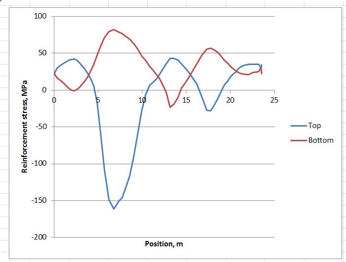
The resulting graph is shown below; note the reduced stress in the regions with additional reinforcement.
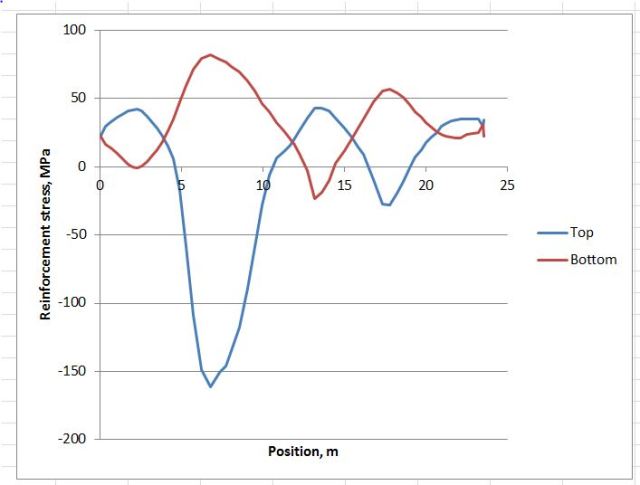
Reinforcement stresses around arch structure
The third example illustrate how a section with varying depth can be analysed, without entering the full section details for every cross section. In the screen-shot below the section depth has been added in Column C:
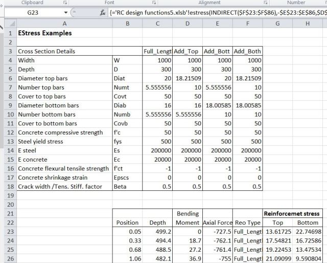
The full function is now:
=’RC design functions6.xlsb’!estress(INDIRECT(F23:F86),-E23:E86,D23:D86,1,2,,,C23:C86)
The range C23:C86 specifies the section depth (in mm), and this overrides the value specified in the section data range. The function again must be entered as an array function.
The examples shown above may be downloaded from EStress Examples.xlsx. Note that the file RC Design Functions6.xlsb should be in the same folder as the examples file, and should be opened first. Estress Examples.xlsx should then be opened, and will link to the RC Design Functions automatically.