Plane Strain FEA – Non linear staged analysis

Continuing the recent series of posts featuring Fortran based FEA routines, the spreadsheet from the previous post has been revised:

  • The spreadsheet allows for a staged analysis, with additional elements placed in layers for any number of construction stages.
  • Temporary loads may be applied to the top surface of each layer, and then removed.
  • The mesh details are entered as node coordinates, and plate node numbers, rather than the automated mesh generation methods used previously.
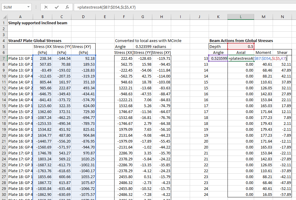
  • The PlateStress4 user defined function (UDF) has been added, allowing beam forces and moments to be extracted from the Gauss Point stresses of plate elements.

The new file, including full open-source code, may be downloaded from:

PlateMC-dll-staged.zip

As before, the spreadsheet requires Python (including Numpy) and xlwings, all of which are included in the free Anaconda Python package.

Example input and results are shown below, featuring analysis of a 10 metre high cantilever retaining wall, with fill placed in 5 stages:

PlaneStrain7-1

Any number of materials may be defined.  Properties are:

  • E: Young’s Modulus
  • v: Poisson’s Ratio
  • c: Cohesion
  • phi: Friction angle
  • psi: Dilatency angle
  • gamma: density (force units)

All plates are 8-noded plane strain elements, with nodes defined in the clockwise direction, starting at the bottom left corner.

PlaneStrain7-2

The construction sequence is defined with the last plate number in each applied layer (column W).  Both plate and node numbers must form a continuous sequence in each layer.  Compaction loads (column Z) are applied to then removed from the top surface of the plates listed in columns X and Y.  The final layer may also have a surcharge load applied to the specified plates as the final load case.

Restrained nodes are indicated with 0 for restrained freedoms and 1 for unrestrained.

Any number of pairs of nodes may be pinned, forcing equal X and Y deflections.

PlaneStrain7-3

Typical results for the example structure are shown above.  The next post will provide more details of results of different soil properties, and also compare results with those from a commercial FEA package (Strand7), and standard retaining wall analysis procedures.

PlaneStrain7-4

Numerical summary results are shown above, including results after placing each layer, and after application and removal of the compaction load.  Total execution time was just over 5 seconds.

PlaneStrain7-5

The spreadsheet is set up to calculate the axial force, bending moment, and shear force over the height of the wall for any specified load case.

PlaneStrain7-6

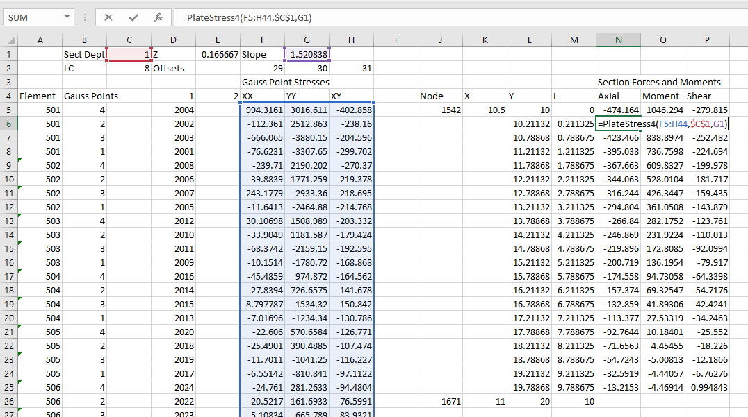
Calculation of the wall actions is carried out on the ConcRes sheet.  The procedure to generate these results is:

  • List the element numbers where results are required, with 4 rows for each element.
  • Calculate the row and column numbers from the StressRes range for the required Gauss points and load case.
  • Use the Index function to return the required stress values.
  • Use the PlateStress4 function to calculate the axial force, bending moment, and shear force for each of the selected plates (see previous post)
Posted in Beam Bending, Concrete, Excel, Finite Element Analysis, Fortran, Geotechnical Engineering, Link to dll, Link to Python, Newton, NumPy and SciPy, UDFs, VBA | Tagged , , , , , , , , , , , | 1 Comment

PlateStress Update

The functions from the PlateStress spreadsheet (details here) will be incorporated in the FEA spreadsheets currently being presented.

In the process of using these functions I made a couple of improvements:

  • The required sequence of the Gauss Points numbers was clarified:
    PlateStress2-1
  • The plate angle input was modified, so that for a straight beam a single value would be accepted:
    PlateStress2-2

Download from PlateStress.zip

Posted in Beam Bending, Excel, Finite Element Analysis, Frame Analysis, Newton, Strand7, UDFs, VBA | Tagged , , , , , , | 1 Comment

Dave Swarbrick

Dave Swarbrick shared with Mark Twain the privilege of saying that reports of his death had been greatly exaggerated.  Sadly, that is no longer true; he died on 3rd June this year, a fact not widely reported in Australia (although he did get a decent obituary in The Sydney Morning Herald).

Here follows a small sample of his work, including two live BBC recordings with the guitarist Richard Thompson, one from 1969 with Fairport Convention, and finally  from the Goodbye Television Centre Concert in 2013:


Posted in Bach | Tagged , , | Leave a comment

FEA slope analysis; effect of mesh size

The last version of the FEA slope analysis spreadsheet (presented here) allows the slope shape and element density to be easily varied.  This post looks at the effect of varying the density from very coarse to fine, with constant soil properties.

The element density was varied from a minimum of 24, up to a maximum of 5600, as shown in the screenshots below:

24 Elements:
PlaneStrain5-2

5600 Elements:PlaneStrain5-3

Calculated maximum deflections with increasing reduction of the soil strength properties (friction angle and cohesion) are shown below:
PlaneStrain6-1
It can be seen that:

  • The coarsest mesh (24 element) shows almost none of the non-linear behaviour found in the other analyses.
  • The 80 element mesh is significantly better, and the 350 element mesh (shown below) gives almost the same results as the two finer meshes.
  • The 1400 and 5600 element meshes gave almost the same results
  • The finest mesh gave the best visual representation of the circular arc of the slip failure surface.

Note that the analysis does not model non-linear geometric effects, and the deformations at the base of the slope are not realistic; nonetheless geometric effects (which are magnified by a factor of 100 in the diagrams) have only a small effect on the overall behaviour.

350 Element mesh:PlaneStrain5-1

Posted in Excel, Finite Element Analysis, Fortran, Geotechnical Engineering, Link to dll, Link to Python, Newton, VBA | Tagged , , , , , , , , , , | Leave a comment

Linking Excel to Fortran with ctypes; update

In the previous post arrays were created in Python and passed to a Fortran dll as ctype pointers.  The data written to these arrays in the Fortran routines was then converted back to Python arrays with statements such as: nodedisp = npc.as_array(nodedisp).  In fact this conversion is not necessary.  The data passed to the Fortran code is a pointer to the location of the arrays created in Python.  The Fortran results are therefore written to these arrays, which may be read directly from Python using the original array names.  More importantly, I found the results of using the npc.as_array() method to be inconsistent; sometimes returning the expected results, but sometimes empty or corrupted arrays.  Reading the results of the Fortran code using the original Python arrays is therefore both simpler and more reliable.

I have updated the previous post to reflect the revised process, and also updated the download file with the revised code.  The new file, including full open-source code, may be downloaded from:

PlateMC-dll.zip

Posted in Excel, Finite Element Analysis, Fortran, Link to dll, Link to Python, Newton, NumPy and SciPy, VBA | Tagged , , , , , , , , , , | 3 Comments