Counting unique values from a range or array

About this time last year, I posted a User Defined Function (UDF) that would return a list of unique items from a list: https://newtonexcelbach.wordpress.com/2012/01/31/retrieving-unique-values-from-a-range-or-array/

That post has recently received a few comments, and coincidentally Colin Legg at RAD Excel has recently posted an article entitled Count Distinct, Unique And Successive Values Using FREQUENCY(), so if you just want to count the number of occurrences of different numbers or strings, rather than return a list of them, using the Frequency() function is the way to do it.

Colin’s article is detailed and clear, and I have nothing to add to it, except to note the different usage of words.  Colin uses “distinct” where I used “unique” to mean one copy of each different number (or string), and “unique” to mean numbers or strings that occur only once.  So in the list “1,1,1,2,2,3” there are 3 distinct numbers (1,2,3) but only one unique number (3).

Posted in Excel | Tagged , , , , | Leave a comment

New Release Alglib Library

The Alglib Numerical Analysis Library has just been updated.  For full details of the changes see: http://www.alglib.net/arcnews.php#date_18_01_2013 , but the significant change for routines linking to my spreadsheets is that the sparse solver  has been significantly improved and now successfully solves problems that previously failed to converge.

If you already have alglibnet2.dll installed just copy the new version over it.  The new version (dated 18/01/2013) is now included in the 3DFrame download: 3DFrame.zip

If you have not yet installed any spreadsheets linking to the C# version of Alglib, see https://newtonexcelbach.wordpress.com/2012/11/16/frame4-now-with-added-alglib/ for detailed instructions on how to do it.

Posted in AlgLib, Excel, Finite Element Analysis, Link to dll, Maths, Newton | Tagged , , , | Leave a comment

3DFrame – 3D Frame analysis for Excel

I have now extended the Frame4 spreadsheet to deal with 3D frames.  As well as making the necessary changes to the input ranges and stiffness matrix generation routines I have revised the Sparse solver routine, added a new compiled solver, and changed to a more efficient VBA solver:

  • In the previous version a full stiffness matrix was generated, which was then converted to hash table format for solving with the sparse solver.  This was not only very inefficient, but also limited the size of problems that could be solved because of the large matrix, containing mostly zero values.
  • For similar reasons the VBA matrix solver routine has been replaced by a much more efficient one taken from “Programming the Finite Element Method” by Smith and Griffiths.
  • The new VBA solver has also been converted to a C# dll, as an alternative to the sparse solver.

The new spreadsheet (including full open-source code) can be downloaded from: 3DFrame.zip

The download zip file includes ALMatrixLib.dll, alglibnet2.dll and ALMatrixLib.tlb which must be installed to use the sparse solver or the compiled solver.  See https://newtonexcelbach.wordpress.com/2012/11/16/frame4-now-with-added-alglib/ for instructions on installing and linking to these files.

Warning:  This software has had only limited testing and is not fully documented.  Do not rely on the output from this spreadsheet for any application where incorrect, ambiguous, or misinterpreted results could have adverse consequences.

Example analyses:

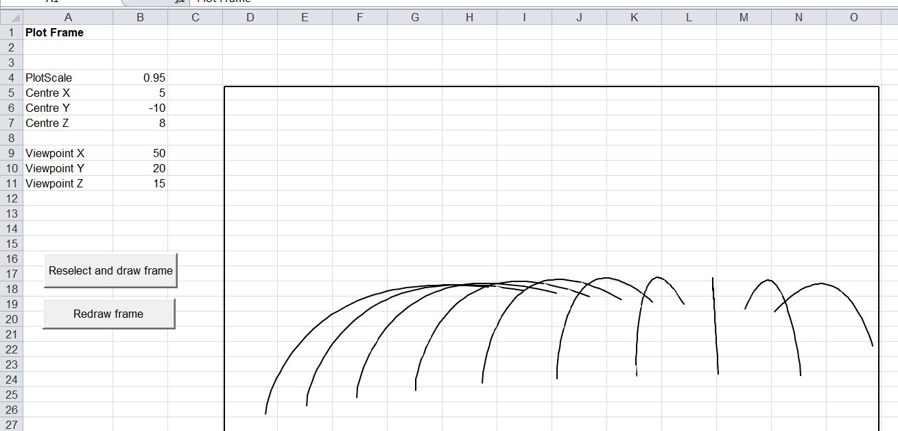
Arch sections rotated about Z axis:

Skew arch units

Skew arch units

The bending moment (due to self-weight) about Beam Axis 2 is the same for each arch:

3DFrame1-2

Bending moment due to self-weight

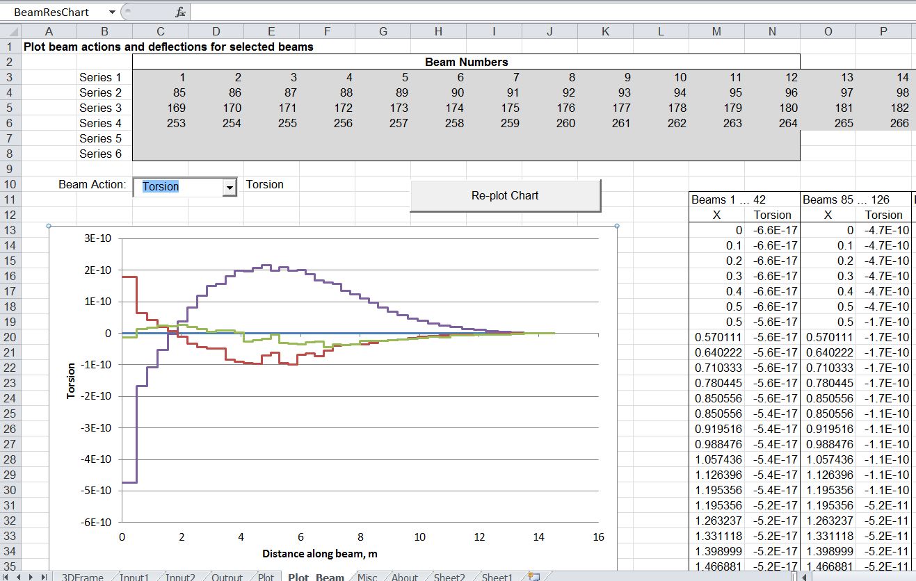
Torsional moments are very close to zero for all arches:

3DFrame1-3

Torsion moment

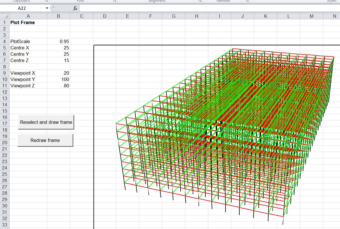
Large frame model (2730 nodes and 7065 beams)

3DFrame1-4

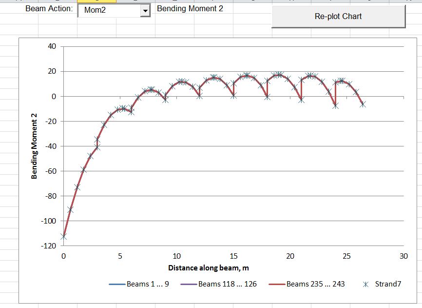
Results for 3 strings of columns compared with Strand7 results

3DFrame1-5

Solution times for the three solvers:

Large Frame Solution Time (solver only)

Large Frame Solution Time (solver only)

These times are for solution of the frame stiffness equations only; setting up the matrix and extraction of the results is performed entirely in VBA and took about 10 seconds for the large frame model. Nonetheless the sparse solver gives dramatic reductions to the solution time, which would potentially make non-linear analysis of even very large models practicable with this spreadsheet.

Posted in Beam Bending, Excel, Finite Element Analysis, Frame Analysis, Link to dll, Newton, Strand7, VBA | Tagged , , , , | 21 Comments

Extracting a hyperlink

Excel does not have a function to extract the address from a cell containing a hyperlink.  Here is a short UDF that will do the job:

Function HLink(rng As Range, Optional RtnSub As Boolean = False) As String
'extract URL from hyperlink
'Orinal from http://blog.contextures.com/archives/2010/12/13/get-the-url-from-an-excel-hyperlink/
 'posted by Rick Rothstein
 'Modified by Doug Jenkins

    If rng(1).Hyperlinks.Count Then
        If RtnSub = False Then
            HLink = rng.Hyperlinks(1).Address
        Else
            HLink = rng.Hyperlinks(1).SubAddress
        End If
    End If
End Function

The original was a one-liner posted by Rick Rosthstein on Debra Dalgleish’s Contextures Blog.  I have just added an option to return the “sub-address” (part following the #), rather than the main address.  Follow the link to Contextures for more suggestions and VBA code for working with hyperlinks.

Posted in Excel, UDFs, VBA | Tagged , , , | Leave a comment

Defining beam orientation in 3D

The principal axes of a beam (or any 2D closed shape) are defined as the axes along which an applied load will not cause any deflection in the transverse direction.  In mathematical terms, if the beam cross-section is defined in the XY plane, then the product of area Ixy is zero when the principal axes are coincident with the X and Y axes.  See Fundamentals of Beam Bending for more details.

In a 2D frame analysis it is assumed that one of the principal axes of  each beam is in the plane of the analysis, so that in-plane loads do not cause any out of plane deflection.  In a 3D analysis deflections in all 3 directions are taken into account, so it is necessary to define the orientation of the principal axes to the global axes used to define the beam positions.  One way to do this unambiguously is to define each beam with three nodes, where nodes 1 and 2 define the longitudinal axis and direction of the beam, and the plane defined by all three nodes defines the plane of Principal Axis 1.   This procedure requires significant additional data input, and since in most cases the planes of the principal axes will be vertical and horizontal, it is possible to define default directions for the principal axes, and then provide an angle of rotation for any beams where the principal axes do not lie in the default directions.  This procedure is quick and convenient, but it is important to know the details of the convention used by each frame analysis program, and understand the effect of this convention on the model generated.

As an example, the FEA program Strand7 defines the default principal axes as follows:

The default orientation for Beam2 elements is defined by:
i3 – is the unit vector directed from Node 1 to Node 2.
 i2 – is the unit vector arising from i2 = Z × i3 where Z is the unit vector in the global Z direction
 i1 – completes the right-handed system such that i1 × i2 = i3

This procedure in effect creates an Axis-2 parallel to the XY plane, and an Axis-1 in the plane parallel to the Z axis; i.e. the Z axis is in effect defined as the vertical axis in the model, and the XY plane is horizontal.  It is important to understand how these axes relate to the default axes of standard beam cross sections, and also to understand the effect of using the Y axis as the vertical, rather than the Z.  In the examples below an arch section has been modelled with different assumptions for the axes directions to illustrate the effect on beams that are not parallel to the global axes.  The arch section has been modelled with sections at the base and top using an I beam section to illustrate  the effect of various options on the direction of the web.

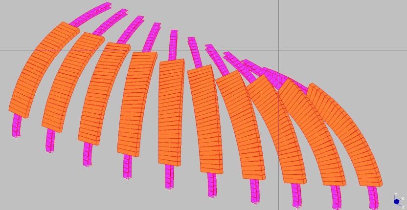
The first screen-shot shows the effect of constructing the model with the Y axis as vertical, and no adjustment of the principal axis angles:
Y Axis vertical, no rotation

The arch on the left is parallel to the X axis, and all the beam members are oriented as intended, but as the angle of the arch vertical plane is rotated through 90 degrees, the angle of the principal axes is also rotated, which is not what is required.

BeamAxes2

Detail at crown, right hand end

Also note that at the right end, the end segment is parallel to the Z axis, and for this one member the beam web is vertical, whereas for the other members lying in the YZ plane, but not parallel to the Z axis, the beam web is horizontal.

BeamAxes3

Z axis vertical

 For a model with the Z axis vertical the beam Principal Axis-2 is created horizontal (parallel to the XY plane), but in this case the default orientation of the I beam webs, and the rectangular section breadth, is parallel to the Principal Axis-1, which is not what is required in this case.

BeamAxes4
Also note that the members at the base, which have a longitudinal axis parallel to the Z axis, are rotated relative to the other members.

BeamAxes5

Z Axis vertical, beams rotated by 90 degrees

Where the Z axis is vertical the correct orientation of the I-beam webs, and the rectangular section breadth, can be obtained by rotating the principal axis through 90 degrees, for all but the vertical beams.

Y Axis vertical

Y Axis vertical, beams rotated by varying amount

Where the Y axis is vertical each beam segment (other than those in the XY and YZ planes) must be rotated by a different amount.  In Strand7 the Tools-Align-Beam Axes command will perform this task automatically, as illustrated above.

BeamAxes7

Correction of the orientation of the vertical beams at the base

For both the vertical Y axis and Z axis the beams at the base must be oriented individually, because the Principal Axes 2 are aligned with the Y axis.

Posted in Beam Bending, Coordinate Geometry, Frame Analysis, Maths, Newton | Tagged , , , , | Leave a comment