Bleeping Computer report that Microsoft have announced JavaScript UDFs for Excel. See the link for more details.
This feature is not yet available in standard Excel, but a preview version is available to those joining the Office Insiders Program.

Bleeping Computer report that Microsoft have announced JavaScript UDFs for Excel. See the link for more details.
This feature is not yet available in standard Excel, but a preview version is available to those joining the Office Insiders Program.
The spreadsheet IP2_py provides a large number of geometric functions, including intersection points of lines, circles and planes, interpolation, rotations, and converting between coordinate systems. Many of the functions are available in VBA and Python versions. The Python code has now been updated to work with Python 3. The updated files can be downloaded from:
Examples of the included functions are shown in the following screenshots:
IP() and IP_4 find the intersection points of 2 lines or polylines:

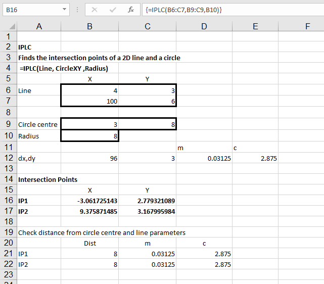
The Circle Functions sheet contains functions to find the intersection points or lines, circles and spheres, and the 3D centre of circles or arcs:
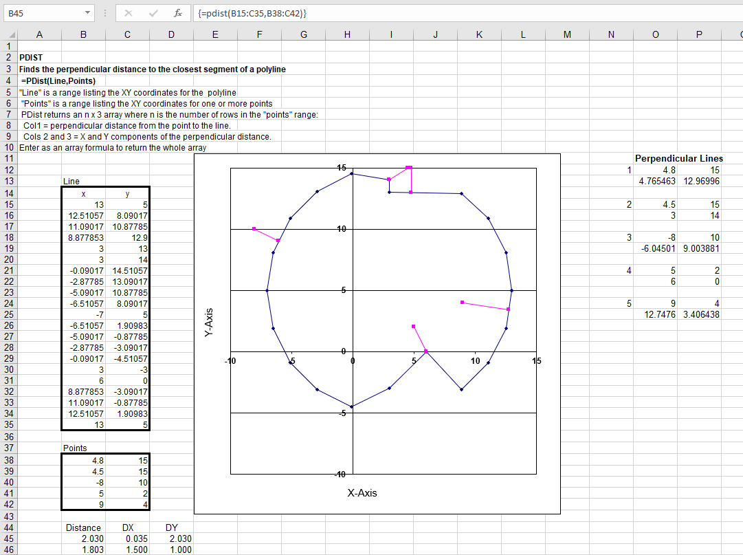
The PDist function returns the perpendicular distance from point to a polyline:
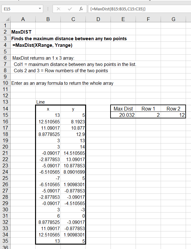
MaxDist returns the maximum distance between any two points in a list:
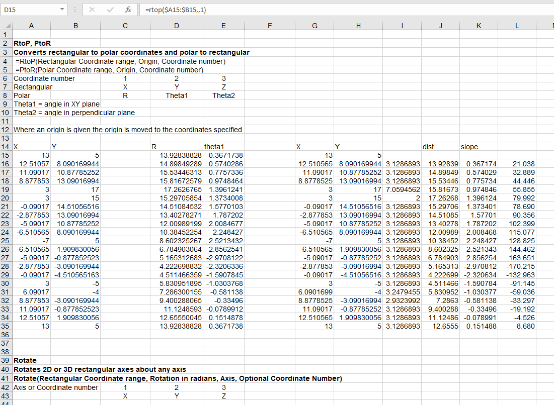
RtoP and PtoR convert coordinates between rectangular and polar systems. Rotate returns coordinates of one or more points, rotated about a specified axis:
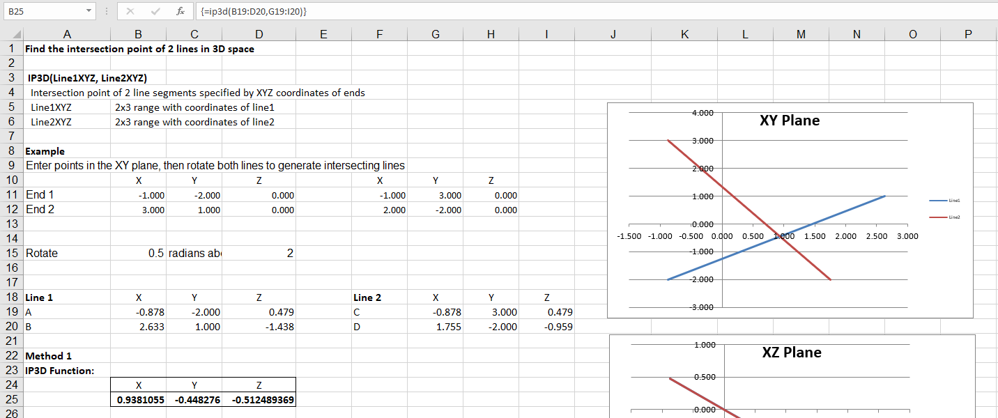
IP_3D finds the intersection point of two 3D lines:
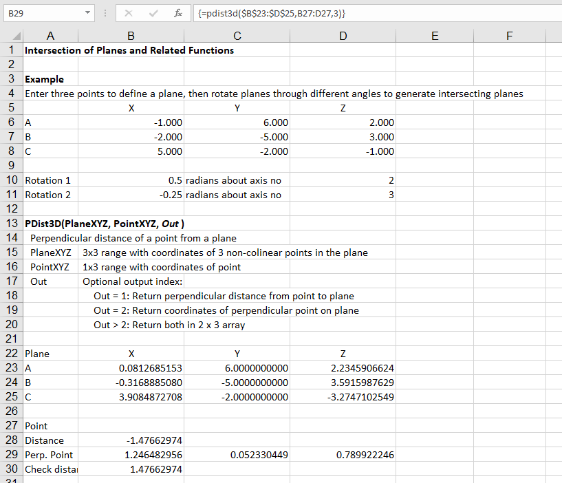
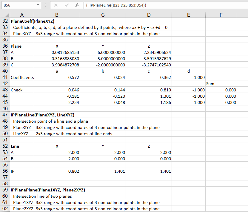
The 3DPlaneIP sheet contains functions to find the intersection of planes and related functions:
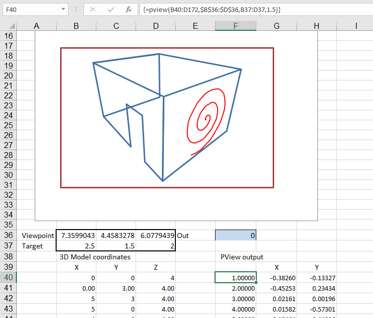
The PView function returns a perspective projection of coordinates viewed from a specified angle and distance.
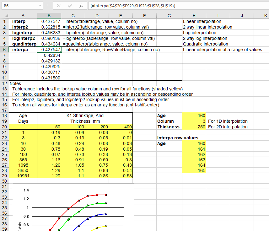
The Interp functions provide linear, logarithmic and quadratic interpolation in 1 or 2 dimensions:
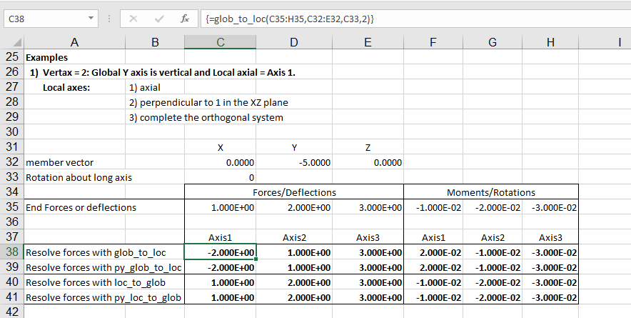
The Glob_to_Loc and Loc_to_Glob transform vectors between different coordinate systems:
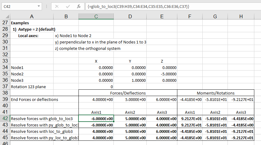
Glob_to_Loc3 rotates plate or 3 node beam deflections or forces between global and local axis systems:
Fit_Circ3D returns a least-squares fit of a 3D circle or arc to a set of points:

The Python based functions require Python, Numpy and xlwings. These are installed by default in the Anaconda Python installation.
A quick and convenient way to allow for the effect of deformations on the behaviour of beams and columns under axial load is to adjust the beam stiffness matrix, so that the calculated deflections are in equilibrium with the applied loads, including the eccentricity of the axial load due to the transverse deflections. Further background to this approach is presented in the book linked in the previous post: Matrix Structural Analysis.
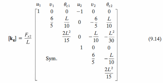
The geometric stiffness matrix for a 1D beam (from the link above) is:
I have incorporated this approach into a spreadsheet that will calculate deflections, shear forces and bending moments for a beam subject to combined axial load and a uniform transverse load. The spreadsheet, including full open source code, may be downloaded from:
Note that the spreadsheet uses the Strand7 axes convention, which changes the sign of some of the matrix values:

Input and output for the Axbeam function is shown below. The beam may be subdivided into any number of segments, each of which may have different materials properties. Deflections or shear forces and bending moments are output at the end of each segment.

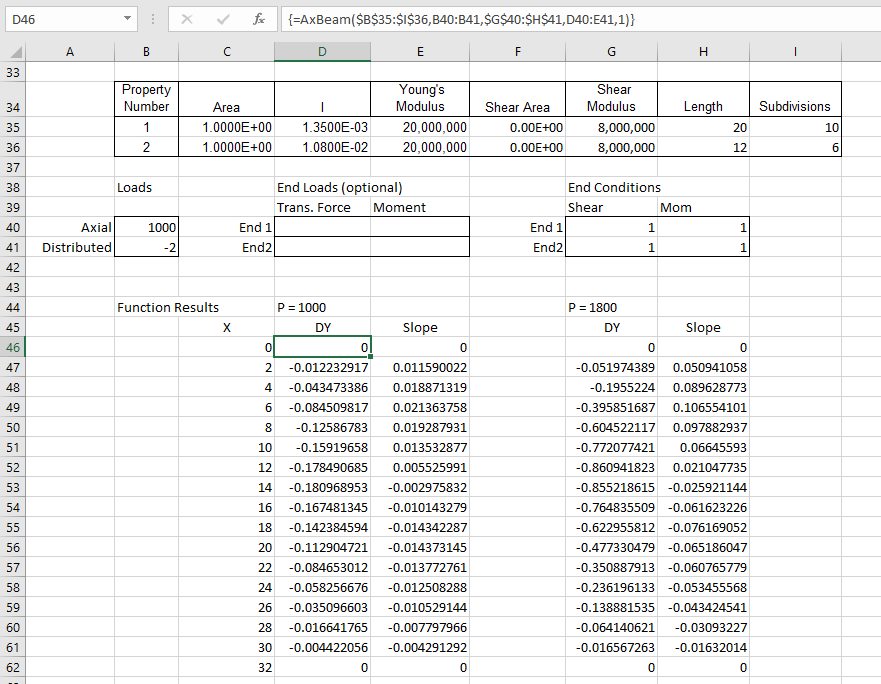
Typical input and output is shown below for a beam with 16 segments, and 2 different material properties. Results are shown for an axial load of 1000 kN, and also 1800 kN, which is close to the buckling load:
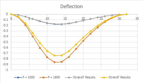
Output deflections are shown below for the two load cases, compared with results for the same beam in Strand7. For the lower load the results are almost identical. For the higher load the iterative procedure used in Strand7 has resulted in significantly smaller deflections:
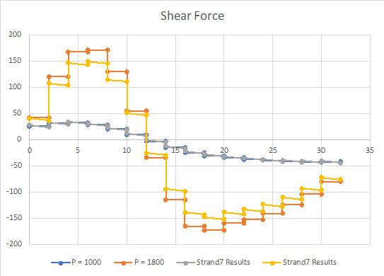
A similar trend is seen for bending moments and shear forces:

The MaxDefAx function returns the maximum absolute deflection for a series of axial loads. In the example below the beam has the same EI value over the full length. It can be seen that the predicted buckling load matches the Euler buckling value very closely:

The beam end conditions may be adjusted. In the example below the moment fixity has been removed at both ends. The spreadsheet buckling load again matched the Euler value almost exactly (the maximum value in the table has been reduced below the buckling load, to show the shape of the deflection curve more clearly). When one or more end fixities are released, end loads may be applied to that freedom.

I recently discovered:
Matrix Structural Analysis, 2nd Edition, by McGuire, Gallagher, and Ziemian.
which is available for free download:
Description
The aims of the first edition of Matrix Structural Analysis were to place proper emphasis on the methods of matrix structural analysis used in practice and to lay the groundwork for more advanced subject matter. This extensively revised Second Edition accounts for changes in practice that have taken place in the intervening twenty years. It incorporates advances in the science and art of analysis that are suitable for application now, and will be of increasing importance in the years ahead. It is written to meet the needs of both the present and the coming generation of structural engineers.
The book includes a link to a free Matlab based frame analysis program:
For those without Matlab, there is a compiled version (also free).
The xlwSciPy spreadsheet allows a wide variety of the science and maths functions in the Python Numpy and Scipy libraries to be called directly from Excel. The spreadsheet has now been updated for use with Python 3. The spreadsheet and all associated Python code can be downloaded from:
The spreadsheet requires installed copies of Python, including Numpy and Scipy, and xlwings. The easiest way to install the required packages is to install the Anaconda Python library. When the required Python packages are installed simply copy the contents of the xlwSciPy3.zip file to any convenient folder.
The functions included in the spreadsheet are indexed below:


