… not full length anyway.
This post was inspired by a now very long discussion at Eng-Tips on the apparently simple question of what happens when you place one short beam on top of a longer one, and apply a load to the top beam. How do the beams deflect, and how is the load shared between the beams, or does the top beam make no difference, since all of the load must go through the lower beam, before it reaches the support?
To keep things (relatively) simple, I will consider here a 10 metre long beam with a shorter beam placed symmetrically about the centre line, with a uniform distributed load over the full length of the upper beam. If the upper beam is sufficiently stiff it will simply span across the centre of the lower beam, transferring the applied loads as point loads at its ends. More interesting is what happens if the top beam stiffness is reduced so that it touches the lower beam in the middle, as well as both ends.
I have analysed this situation using the SSSPanU function from the ConBeamU spreadsheet. A modified version of ConBeamU including the analysis described here can be downloaded from ConBeamU-2Beams.zip.
The procedure used in the analysis is:
Assuming two beams, the top one shorter than the bottom, arranged symmetrically about mid-span, with the top beam subject to a UDL of its full length.
- Check if the beams contact at mid-span. If they do not, or if it is a point contact, find the moments in both beams from statics. If they do contact over a finite length:
- Find the total moment at mid-span from statics
- Distribute this moment in proportion to the beams EI values.
- Assume some contact length, symmetrical about mid-span.
- Starting from the mid-span moments, find the moments in both beams at the start of the contact length
- Calculate the point force transfer at the start of the upper beam required for static equilibrium with the calculated moments.
- Find the point force transfer at the start of the contact length required for overall static equilibrium.
- Apply these loads to both beams assuming point contact of the ends of the upper beam on the lower beam.
- Calculate the difference in deflection at mid span, relative to the ends of the upper beam.
- Adjust the contact length until the difference in deflection is zero.
The spreadsheet allows this procedure to be carried out quickly, using the Excel Solver.
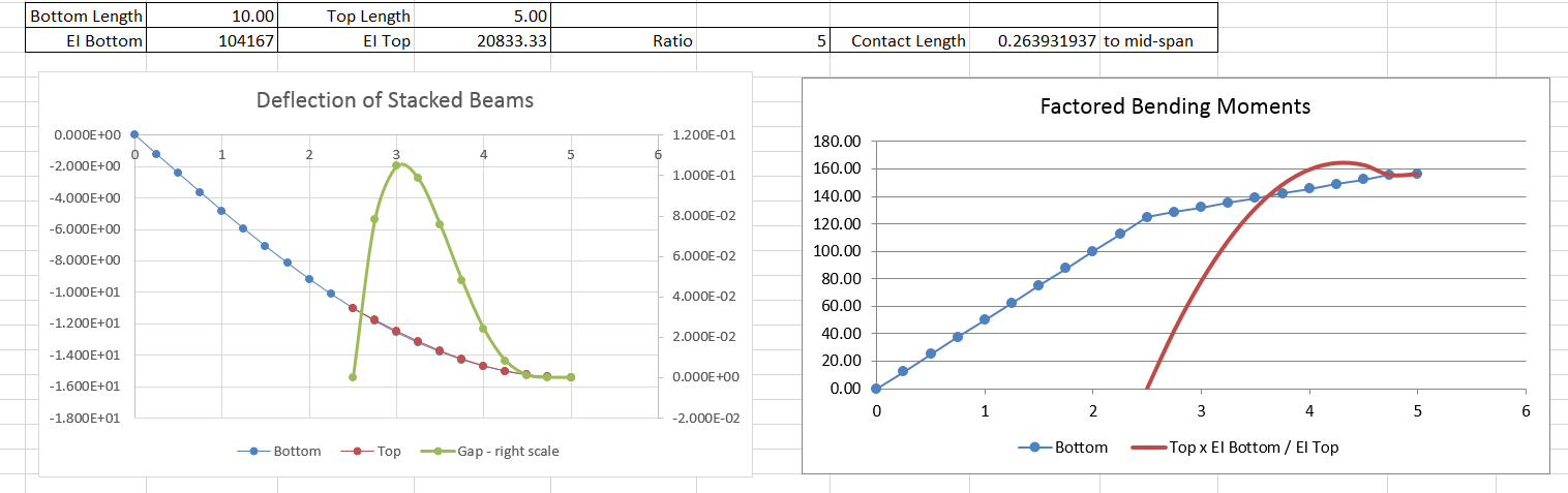
The beam lengths, EI of the lower beam, and relative stiffness factor of the two beams (EI Lower / EI Upper) are entered:

The spreadsheet calculates the point load transfer at the ends of the upper beam, and the ends of the contact zone, specified in cell L2:
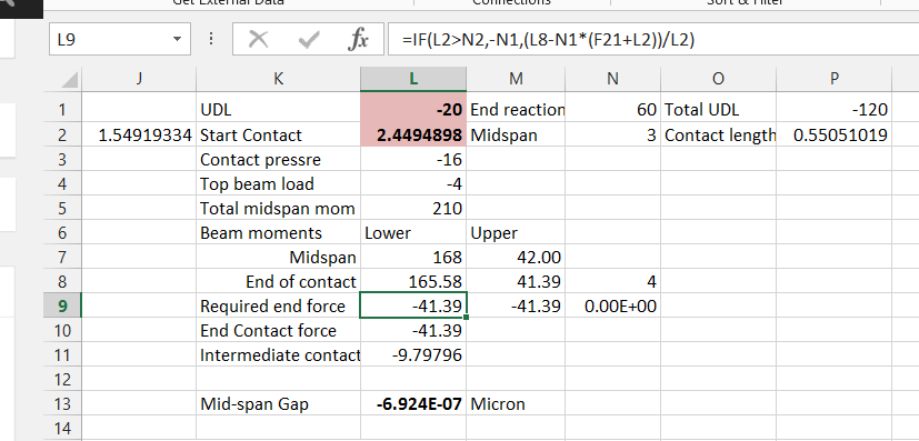
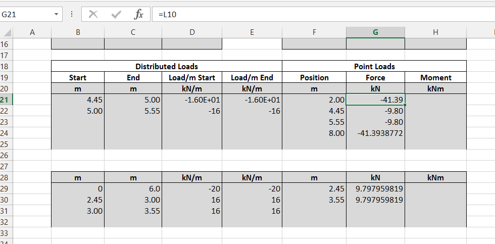
These values are transferred to the input data for two copies of the SSSPanU function:
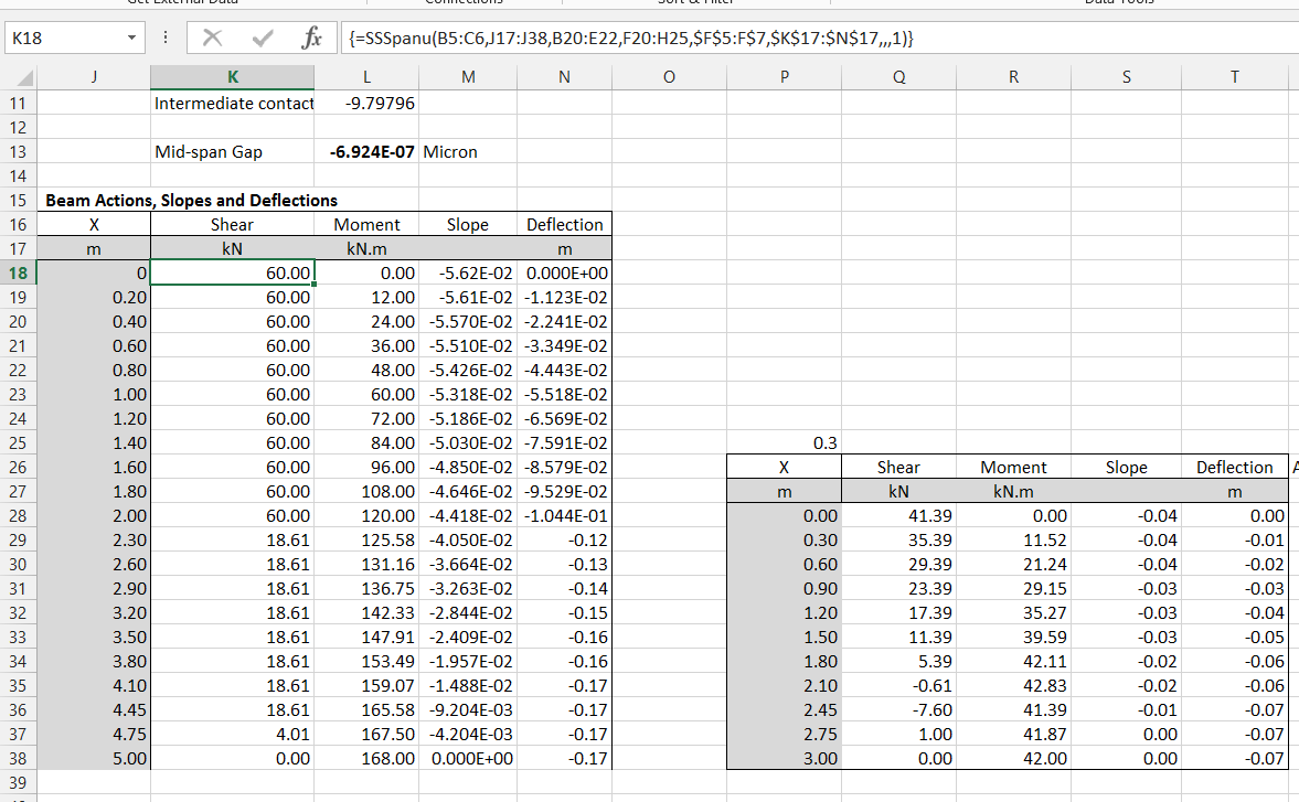
The functions calculate the moments, shears, slope and deflection along both beams. The Excel solver can be used to automatically adjust the start of the contact zone dimension so that the gap between the two beams at mid span is zero:
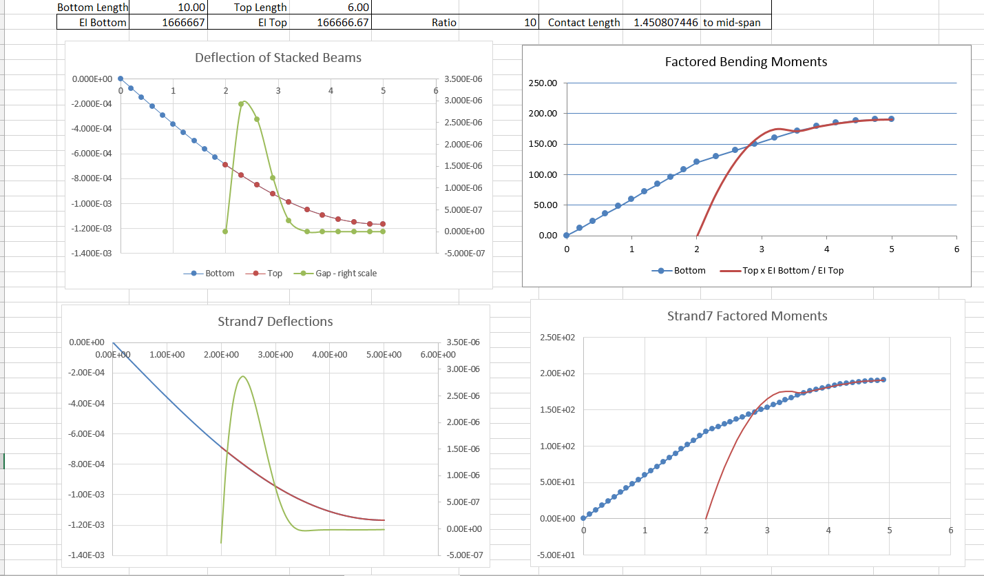
Typical results are shown below, plotted from the left support of the lower beam to mid-span. The green line in the left hand graph is the gap between the two beams (right hand scale). Note that the gap is zero over the contact zone, increases to a maximum, then returns to zero for a point contact at the end of the upper beam. In the moment diagram the upper beam moments (red line) are factored by the beam stiffness ratio. Note that the factored moments of the two beams are exactly equal over the contact zone, because the curvatures of the two beams are equal over this length.
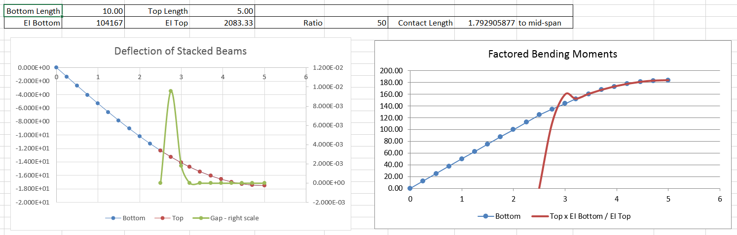
Reducing the stiffness of the top beam increases the contact length, but the moments and gaps follow the same form.
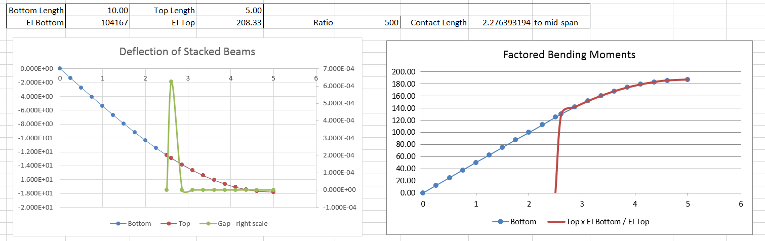
Even reducing the top beam EI to 1/500 that of the lower beam, the contact length does not extend to the top of the upper beam.
These graphs show a comparison of the spreadsheet results with a finite element analysis using Strand7, with the beams connected by short contact elements with zero friction and zero tensile strength. The FEA results agree very closely with the spreadsheet analysis.