
Further to the last post on this subject I have been looking at procedures to speed up design for shear to AS 3600 when the “refined” analysis procedure is used. The issues that need to be addressed are:
- The design shear capacity reduces with increasing tensile strain at the mid-depth of the section, and the tensile strain increases with increasing applied moment and shear force. To find an accurate upper limit to the shear capacity it is therefore necessary to carry out an iterative analysis to match the applied shear force, and associated bending moment, with the shear capacity of the section. This is particularly important for the assessment of existing structures, where it is a requirement to find the actual maximum capacity of the structure, rather than designing for predefined maximum loads.
- The maximum shear capacity may be controlled by the shear failure or by the combined effect of bending, shear and torsion on the longitudinal force on the tensile reinforcement.
- As discussed previously, where the section capacity is controlled by the longitudinal tension force the design capacity can be increased by increasing the angle of the shear compression strut. This also requires an iterative process.
I have now written a Python function to carry out the iterations using the Scipy brentq function with the procedure outlined below:
- From the input data calculate the ratios: moment/shear (M/V) and torsion/shear (T/V)
- Adjust the shear force and associated actions so that the applied shear force equals the design shear capacity.
- If the design bending capacity, reduced for the longitudinal force due to shear and torsion, is greater than the applied moment then return the results, else:
- Set the shear compression strut angle to the maximum value allowed by the code (50 degrees) and adjust the shear force and associated actions so that the applied moment is equal to the reduced design bending capacity.
- If the design shear capacity is now greater than the applied shear force then return the results, else:
- Adjust the shear compression strut angle so the ratios Applied Shear/Design Shear Capacity and Applied Moment/Design Moment Capacity are equal.
- Adjust the shear force and associated actions so that the applied shear force equals the design shear capacity.
- Repeat 6 and 7 until the ratio of applied actions/design capacity equals 1 for both shear and bending.
Typical function output is shown in the screenshot below:
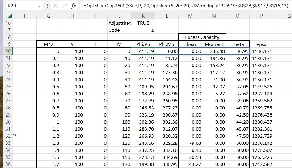
In this example the section has been analysed for a constant shear force with an increasing M/V ratio. The function output (Columns K to O) is:
- Design shear capacity, and the associated bending moment for the input M/V ratio.
- The “excess capacity” for shear and bending. Note that this has three zones where the capacity is initially controlled by shear only, then both shear and moment are at full capacity, then the adjusted bending capacity controls.
- The compression strut angle (Theta). The strain values in Column P are calculated with a simple on-sheet formula.
These results are plotted below with typical shear and bending loads, taken from a heavy road vehicle travelling over an 8 metre simply supported span, with the loads plotted at 0.4 and 1.0 metres from the support. The capacity is also plotted with no adjustment of the compression strut angle, showing a significantly reduced capacity.
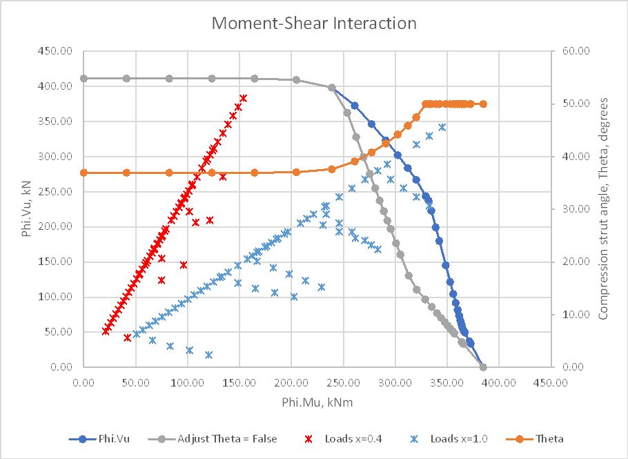
Plotting the section capacity as a moment-shear interaction diagram allows the loads from all sections with identical reinforcement to be plotted on the same section, and load cases where the applied loads exceed the section capacity are immediately visible.
This is a work in progress, but a spreadsheet with all necessary Python files will be available for download shortly.

Pingback: py_UMom spreadsheet and OptShearCap3600 function | Newton Excel Bach, not (just) an Excel Blog
Hi Doug,
Very interesting post, thank you.
I’ve been thinking about M-V interaction cruves and how one might use them in practice when considering also clause 8.2.9 in AS 5100.5.
By way of example, take a simply supported beam with a generic combination of loads. You’ve gone ahead and sized your longitudinal reinforcement such that the bending utilisation is ~100% (M*~= Phi x Mu) at midspan. And for arguments sake the midspan V* is zero. All seems well thus far.
If you then proceed to plot all of the design effects (M*,V*) on the M-V interaction curve produced via the method in this post, then at points close to the maximum moment location you may start to see various “failures” as soon as V* becomes non-zero because there will be additional longitudinal steel required (and thus the bending capacity is reduced). This would seem to immediately contradict 8.2.9.2 at any cross sections considered “adjacent” to the maximum moment region (whatever that means).
If a detailed M-V is the theoretically sound approach (and I think it is), the code should probably move away from the 8.2.9 simplifications, but this would be quite a shift in thinking for designers I suspect?
Cheers.
LikeLike
Thanks for the comment Marc,
I’m actually in the process of writing a paper for the Concrete Conference (due on Thursday) looking at provisions for shear in AS 3600 and AS 5100.
When that is finished I’ll look at doing a post on this issue, but briefly the case you outlined is not normally a problem because the additional bending steel is required at the base of the compression strut, where the moment is less than it is at the section where the shear force is applied.
The codes are not very clear about where this can and can’t be applied however, and are not consistent, so It’s worth looking at in more detail.
LikeLike
Thanks Doug. I will keep an eye out for your paper and upcoming post.
Complicates the M-V interaction method though as you would need to filter out certain results / identify where this may apply. I suppose you design for max bending, then do M-V checks for only sections either side of max bending.
I just created a WordPress account so I can comment more easily :).
LikeLike